|

Applicable to TC-1 to TC-1607, TE-1 to TE-942, Except TE-938
Got blue stains in the tray underneath your
fuel selector? Got blue staining on the body of your fuel selector? See
HERE for examples
of fuel staining of a Bonanza fuel selector body (Click
HERE if you need
Bonanza fuel selector O-Rings).
Did someone quote you an
incredibly high price to OVERHAUL your fuel selectors (I can't understand why,
because there's only o-rings in there that any A&P is authorized to remove and
replace). However, it is a rather tedious and critical process as you will see
in this teardown narrative.
Hopefully, the
below narrative and high resolution images can take some of the intimidation out
of the opening up of one of these beasts by a qualified A&P mechanic.
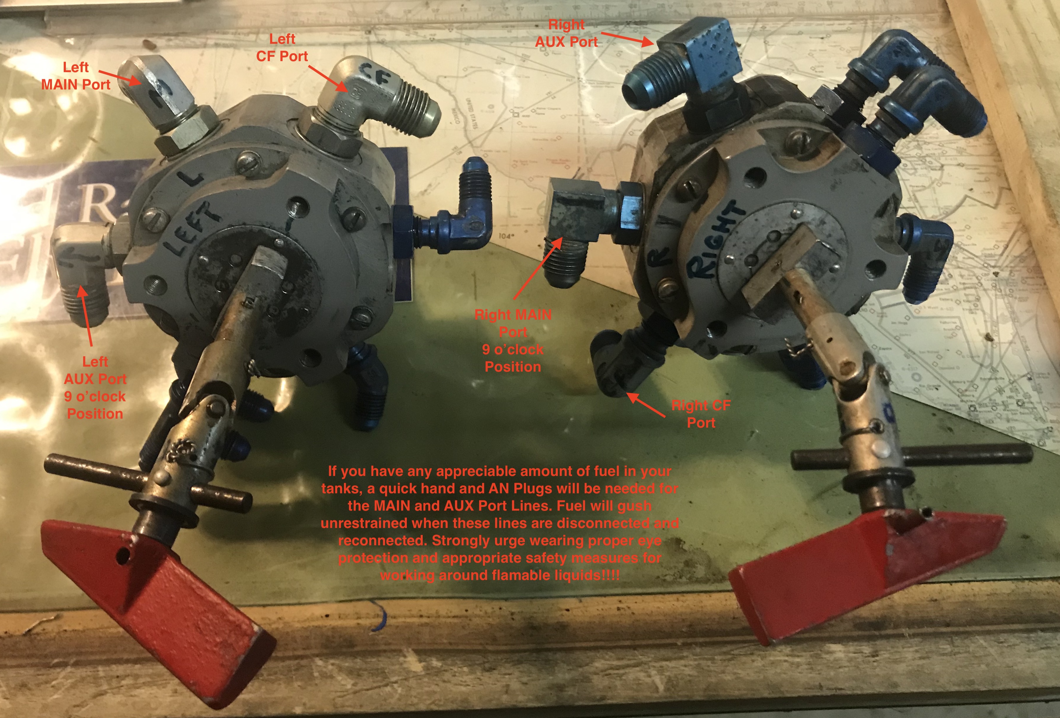
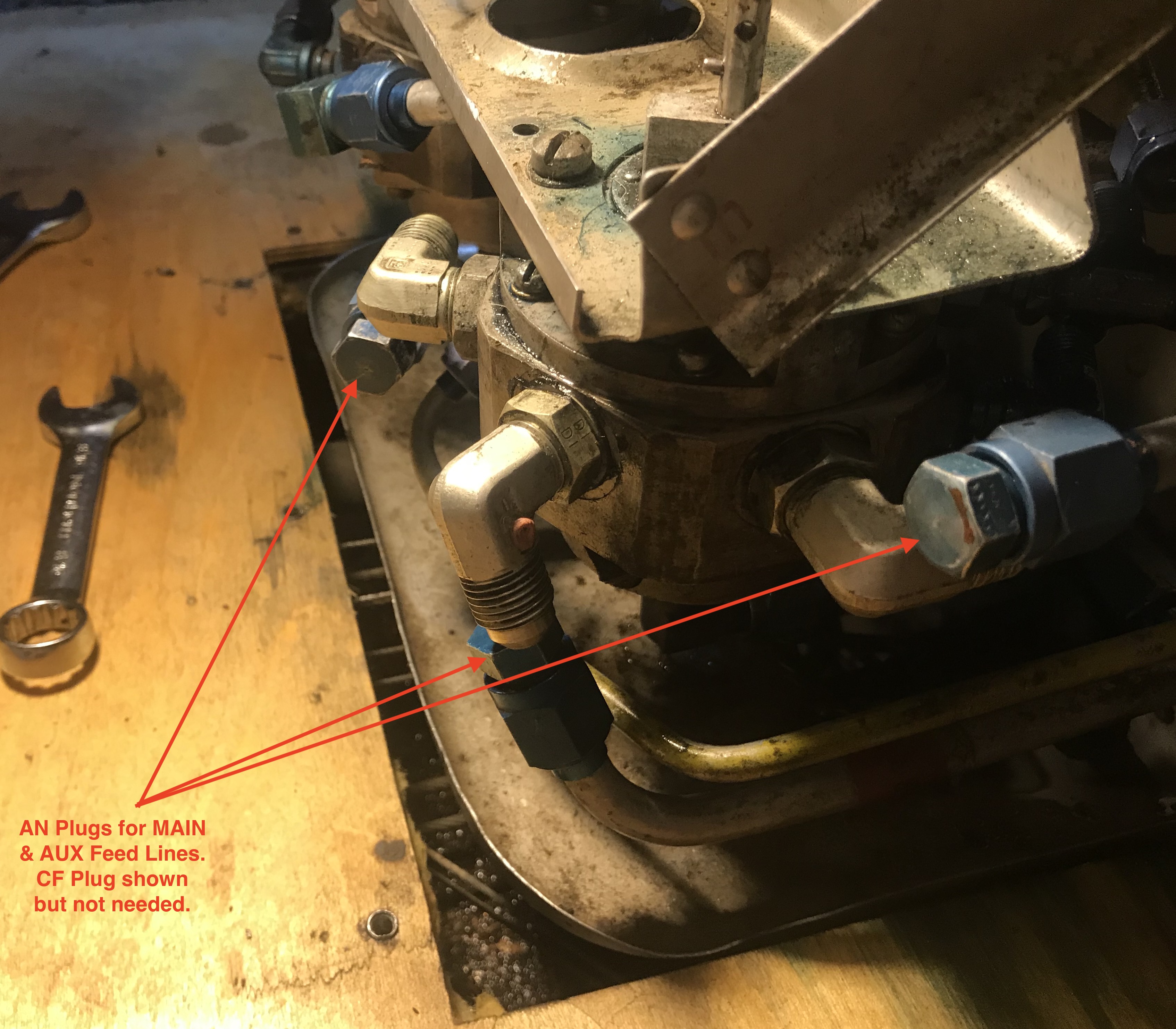
The removal was tedious, especially with
nearly full tanks
 , which
required AN plugs and a very quick hand on the MAIN and AUX feed lines going into the selector valve. , which
required AN plugs and a very quick hand on the MAIN and AUX feed lines going into the selector valve.
Unless you have some form of bent shaft or
selector body warping (highly unlikely), you're in luck, because a simple fix
might just be to replace the o-rings in the selector body.
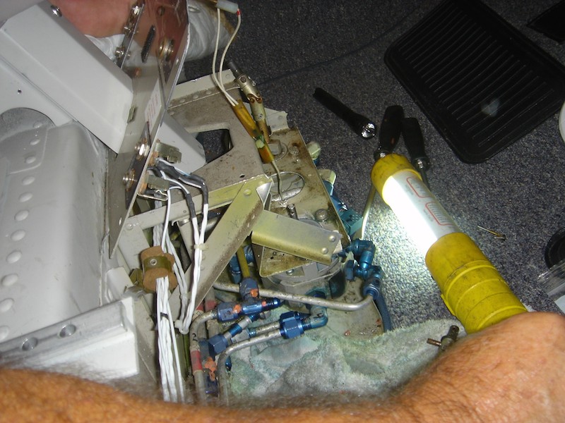
It's a rat's nest of
fuel lines in there and a not so great place to access (stubby 11/16" and 9/16"
wrenches were essential to me in this aspect) but it is doable to
extract these items from their home and open them up on the bench and replace
the o-rings.
Be sure you have the work done by an A&P/IA or are well supervised
by one, as this, like many areas of certified birds, is not an area for
unsupervised amateurs.
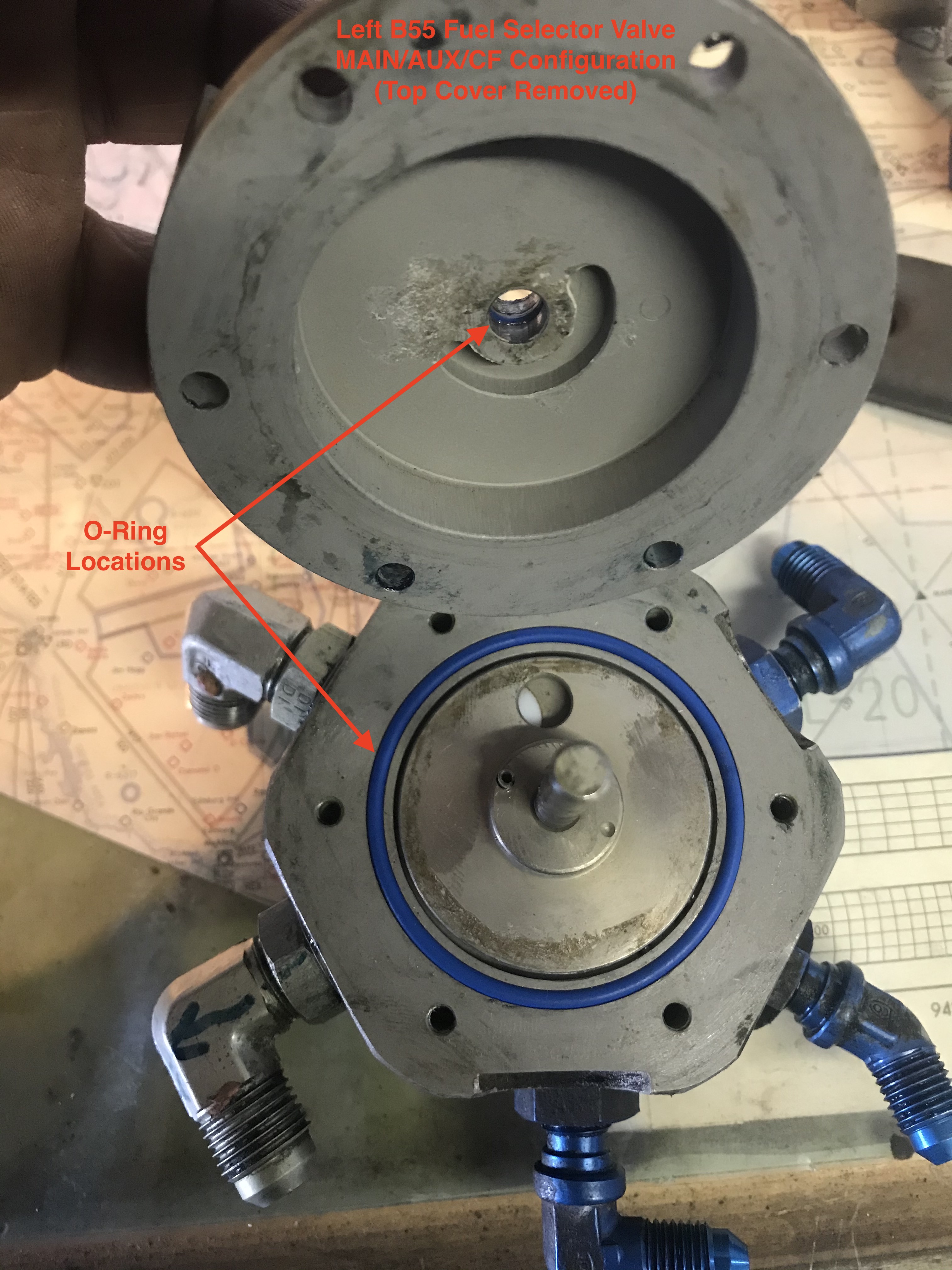
WARNING
It is
EXTREMELY CRITICAL that the orientation of these
components is
preserved for proper functionality!!!! My IA and I
match marked
and photographed everything to insure a proper
reassembly.
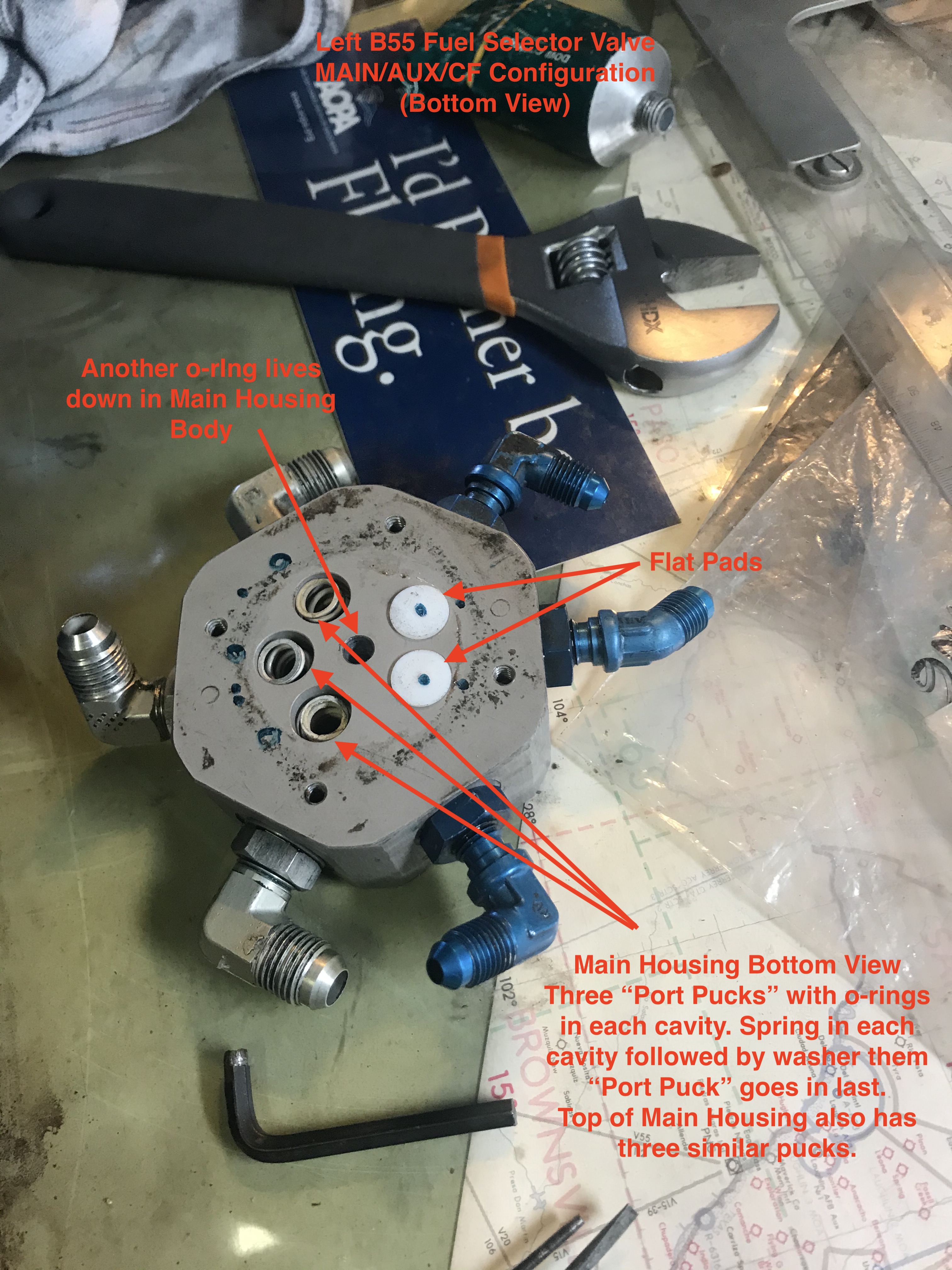
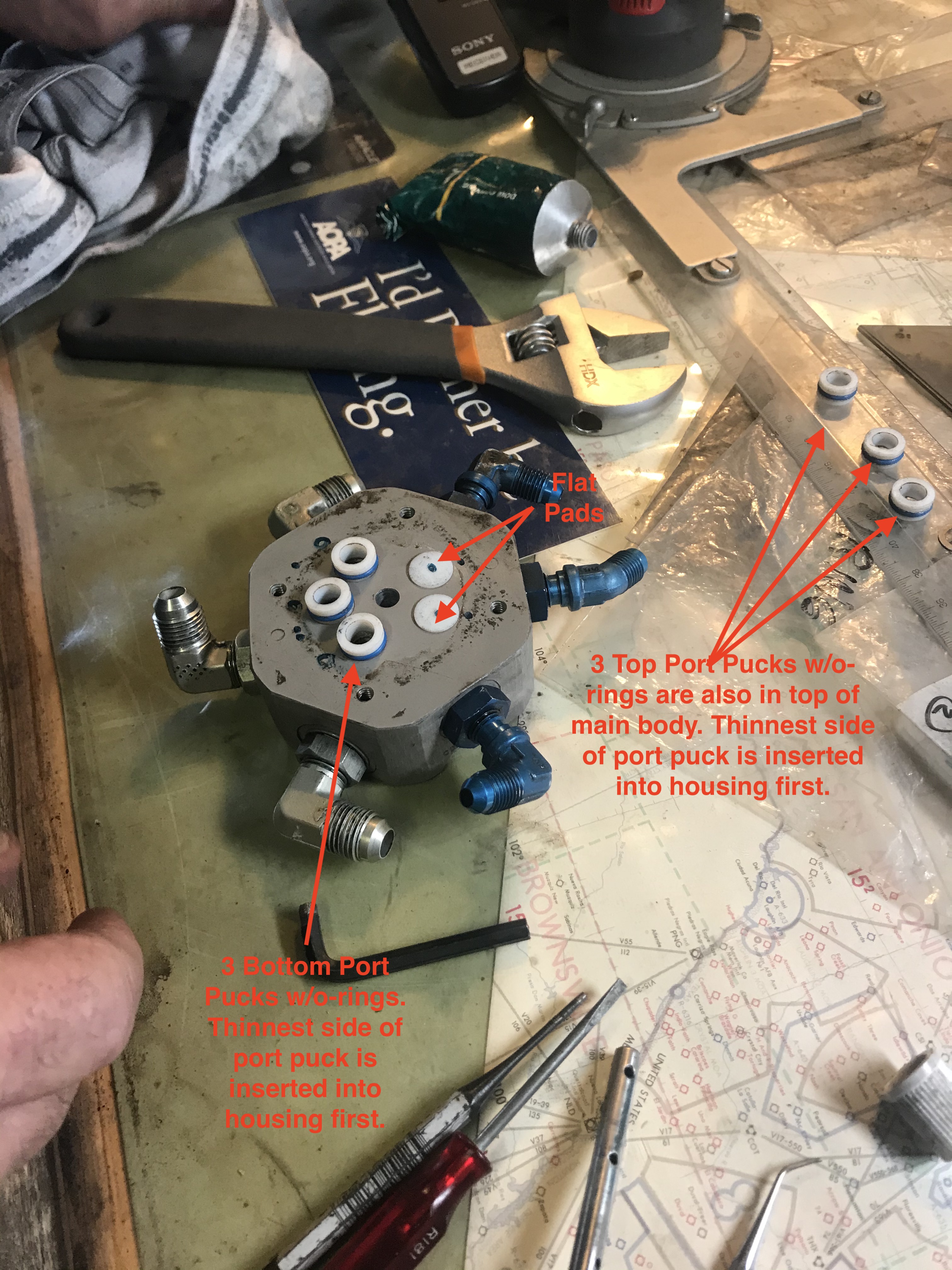
See the B55 MAIN/AUX/CF fuel selector parts extract
HERE for
o-ring details.
See a narrative
HERE written by
B58 owner and A&P, Larry O., on his B58 fuel selector R&R.
See
HERE for some flurosilicone o-ring options for the shaft and body o-rings if
your A&P will authorize a substitution. Flurosilicone o-rings have been shown to
deliver much greater service life than their 1940's nitrile rubber versions.
An IA/Bo Owner (Bob B.) reminds me that the so
called "o-rings" in the fuel line fittings attached to the selector body are in
fact "BOSS SEALS" (Item #26 MS29512-6 in the above fuel selector extract)
and are different dimensionally AND in chemical resistance than conventional o-rings.
He says:
"They have a cross section almost square. MS 28778-xx (in the case of my B55,
MS29512-6). They are a different hardness/durometer than an o-ring also. The
size is a reference to the tubing size for the affected fitting. Thus a -6 is
for a 3/8 fitting which is for most Beechcraft fuel selectors. O-rings are sized
by cross section diameter and inside diameter and classed as fuel or oil. It is
not unusual for mechanics (ought to know better) to assume a 'standard' o-ring
is used. In a way that is correct if one uses 'standard' in reference to the
correct part for the application. This is the Readers Digest version of the
Parker Handbook.
The IPC calls them o-rings, yes. Thus the confusion by
many to use a 'standard' o-ring. The part number MS29512-xx uses a number '4' or
'6' to indicate tube size. It is a tube fitting in the Mil Spec and fuel
resistant, very important distinctions. This is why using the parts manual is
usually the best source for part identification.
Many of us (A&Ps) learned to use the part needing the
o-ring to determine what to order-Measure the cross section, measure the
diameter, look it up on a chart. I have a 20+ year old chart. It gives an
explanation of the applicability for the part numbers and calls the AN & MS
(o-rings) - Boss Gaskets.
MS29512, MILITARY STANDARD: PACKING, PREFORMED,
HYDROCARBON FUEL RESISTANT, TUBE FITTING, "O" RING (01-SEP-1965) [S/S BY
SAE-AS29512].
Not really a tomato-tomato issue. but this is one of
many things that come up the industry will never truly eliminate. When I was in
Corona, only a mile from Aircraft Spruce, this very issue caused a great deal of
heartburn with their parts department. The boys in back packed the o-rings in a
baggy and I refused them. The actual single packages give lot, expiration date,
and clear identification. You can not tell the difference between a MS29513 and
a MS 28775 the same size but one is fuel and the other oil. Although I have seen
them used interchangeably, it is not BEST practice. Many parts are commonly
called by the Brand name regardless of actual manufacturer-Sheet metal screws
called PKs for instance."
"A rose by any other name would smell as sweet"
So be careful not to just replace these BOSS
GASKETS with a
conventional o-ring that looks like it fits!
But anyway, for those who insist,
HERE is a link to a
sizing chart for the MS29512 "boss gaskets" in case you want to "roll your own
in M25988/1-XXX Flurosilicone".
Be sure to secure A&P approval prior to any
O-ring substitution and return to service!
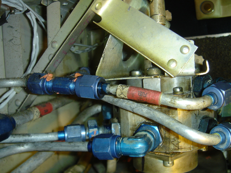
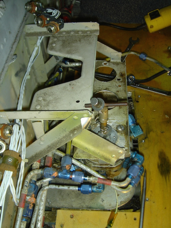
Below is the rat's nest of fuel lines for the
B55 fuel selector that
you'll be looking at:
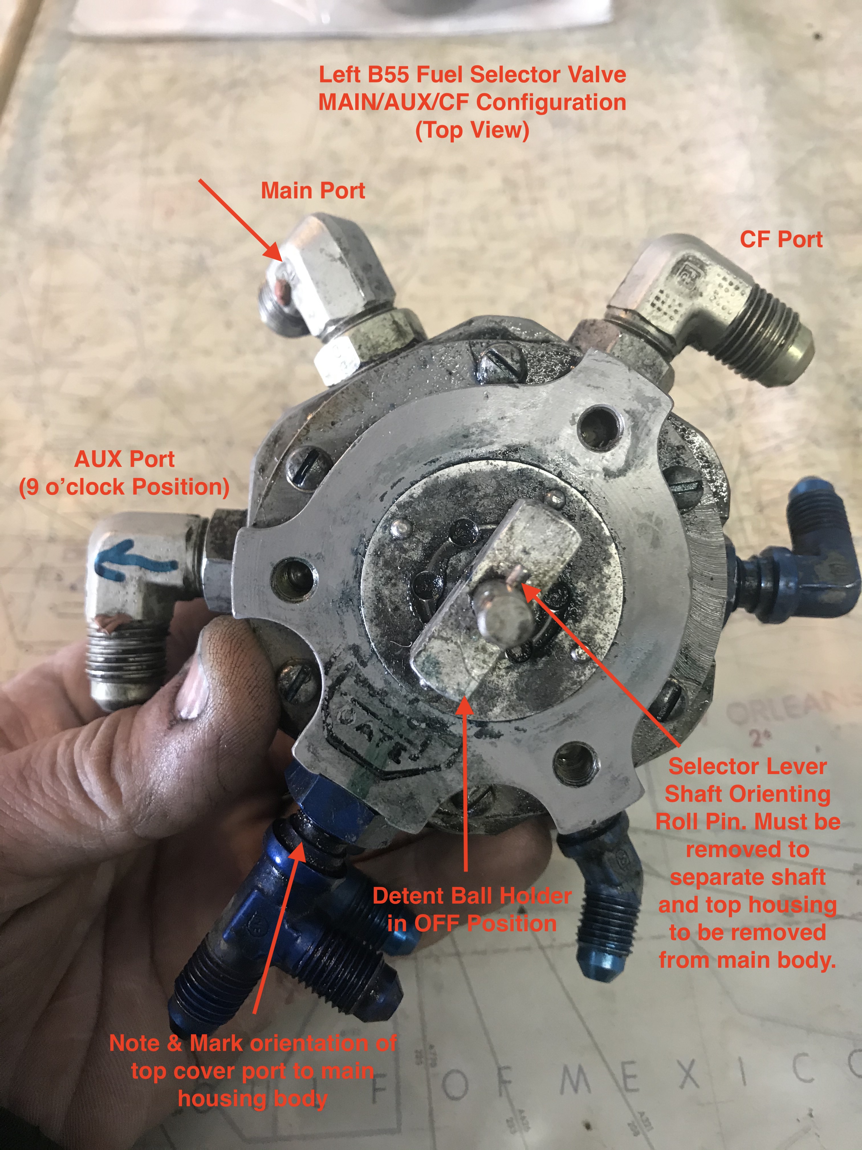
Be sure to put whatever markings, tags or
numbers you feel are needed to get EVERYTHING back in the same orientation! THIS
IS ABSOLUTELY CRUCIAL! Digital
photos are also a big help.
Tips I learned:
1. Have proper size AN plugs on hand (and be
quick of hand to insert plugs) for MAIN and AUX lines or drain fuel tank(s).
2. Wear appropriate eye protection with splash
guards.
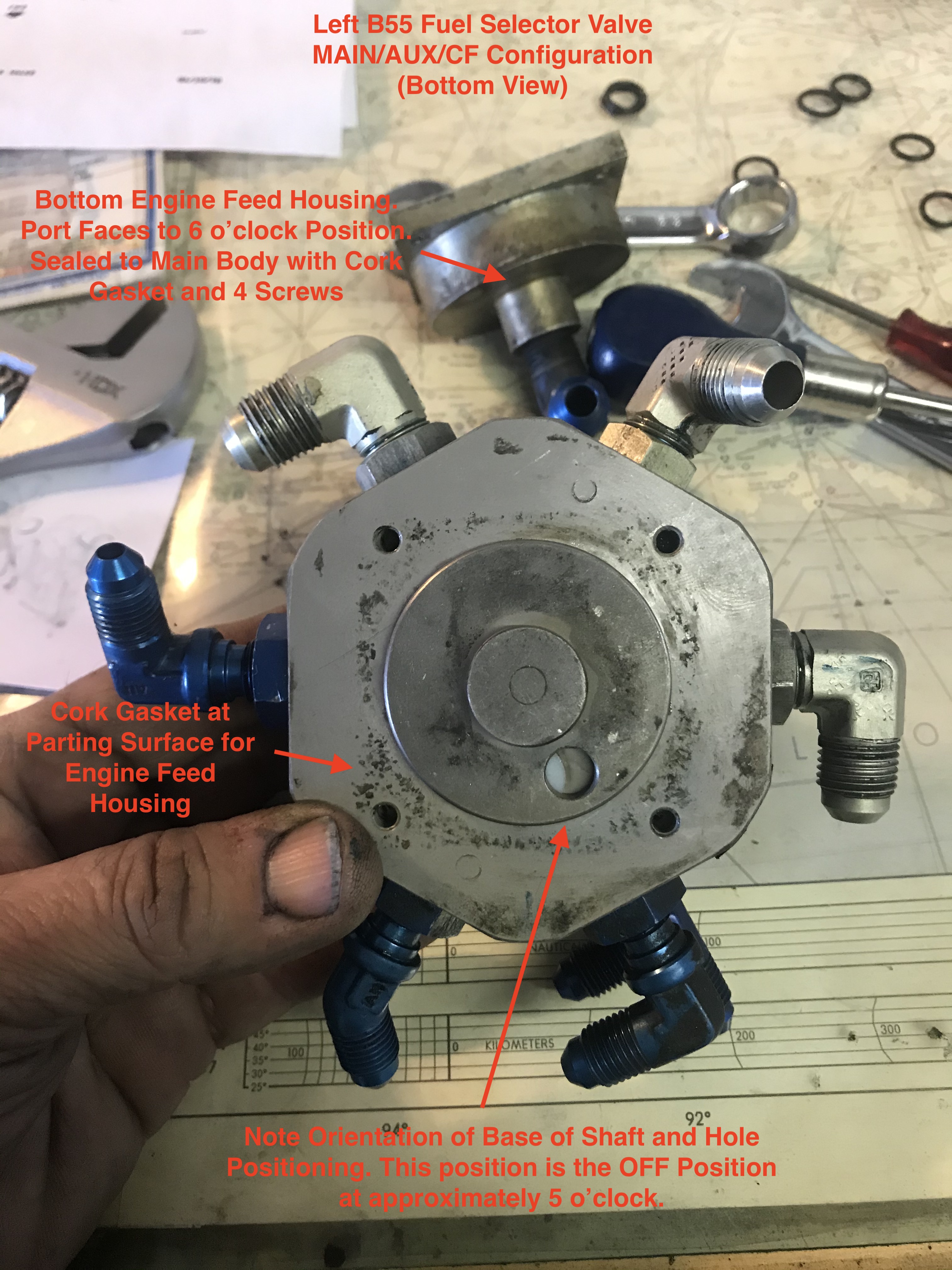
3. Match Mark and/or photograph all parts and
their orientation to each other. Starting with both valves in the OFF position
was helpful in a baseline orientation and prevented fuel from also coming out of
the engine feed port at the bottom of the valve.
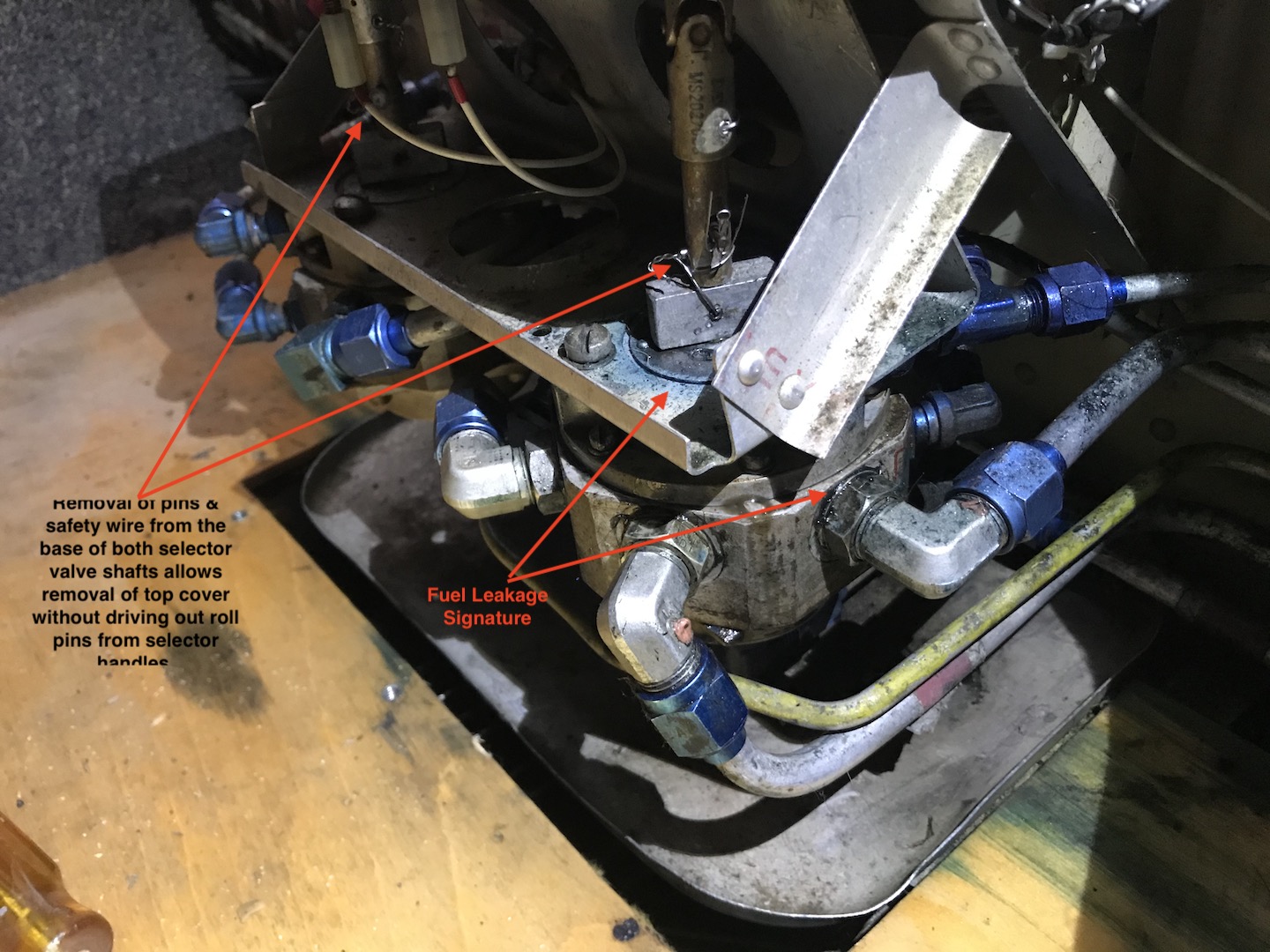
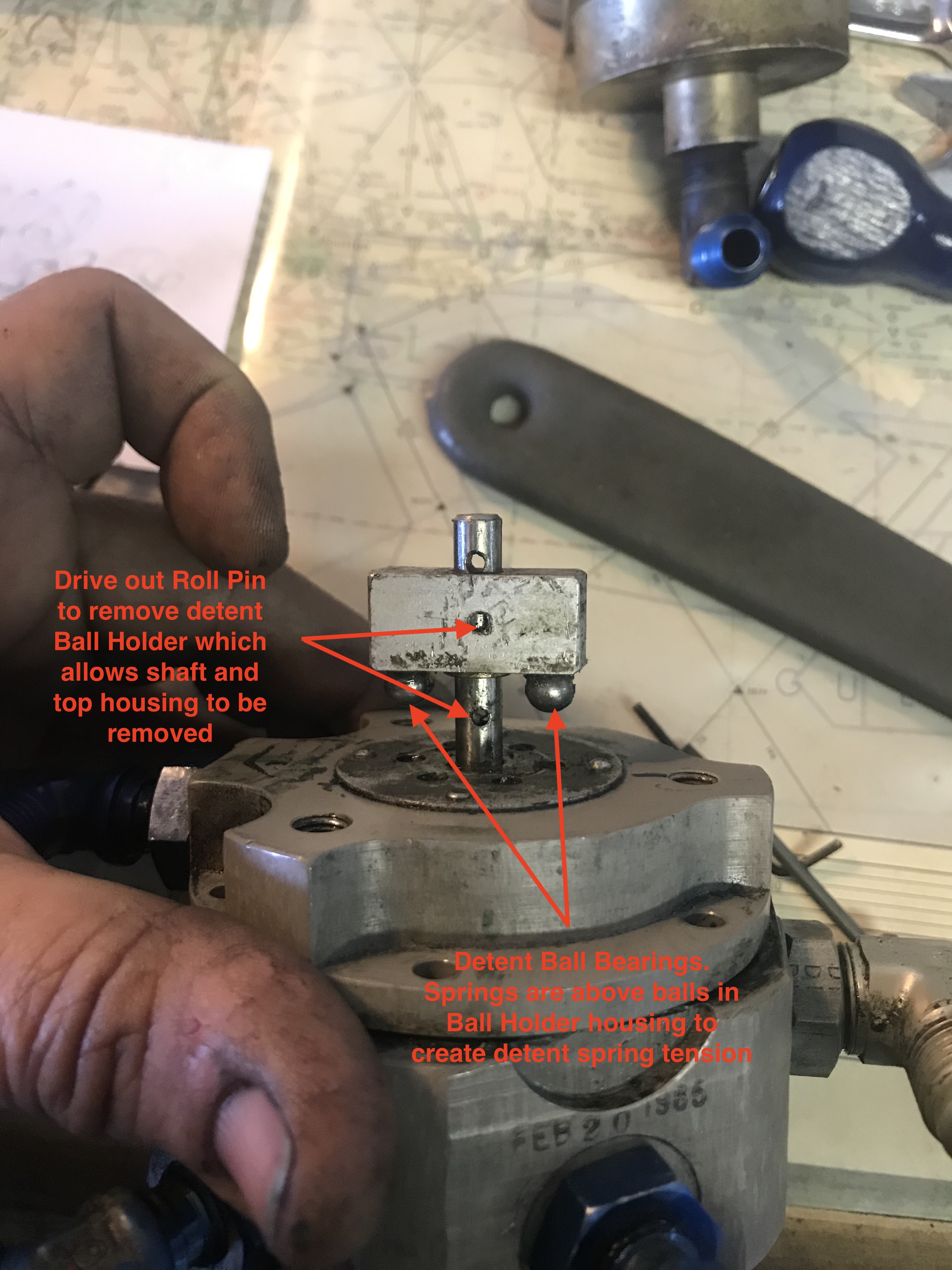
4. Beware of burrs induced in center shaft
(which can damage interior o-rings) as a result of driving roll pins out (a rat
tail file can deal nicely with these).
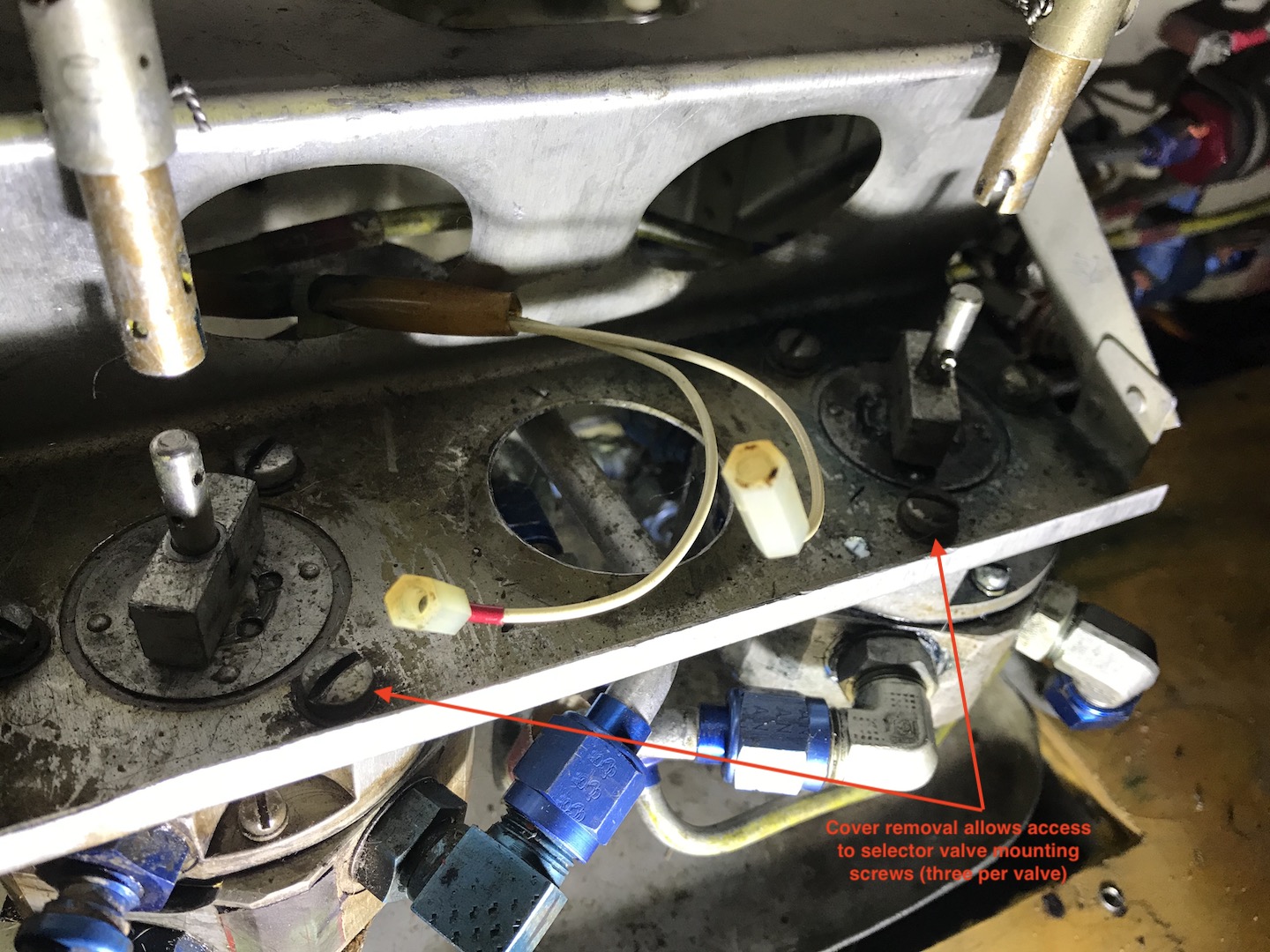
5. Leaving top mount screws in mounting frame
aids in loosening lines to valve.
6. Allowing valve to "float" upon
re-installation, without the top three mounting frame screws attached to
mounting frame, aids in attaching lines to valve.
7. Match mark fitting orientations to enable
proper line orientation and ease of reattachment.
8. Upon final tightening of each line apply
torque putty to identify it as a torqued line.
9. Count the number of fittings on each valve
and confirm that the total matches the number of lines that have torque putty
applied
10. Leave left selector valve out to remove
right fuel selector which allows easier access to MAIN/AUX/CF lines on left side
of the right valve. Re-install right selector valve first
11. Right selector valve is of similar design
but orientation of lines and shaft positioning is different. AGAIN, match
mark/photo everything related to orientation of the valve body housing, center
shaft and port fittings.
Another watch out is to be sure to use some form of
Torque Putty or marker pen or indicator to indicate that you final tightened each line.
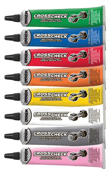
This
will help you confirm that all fittings have been properly tightened.
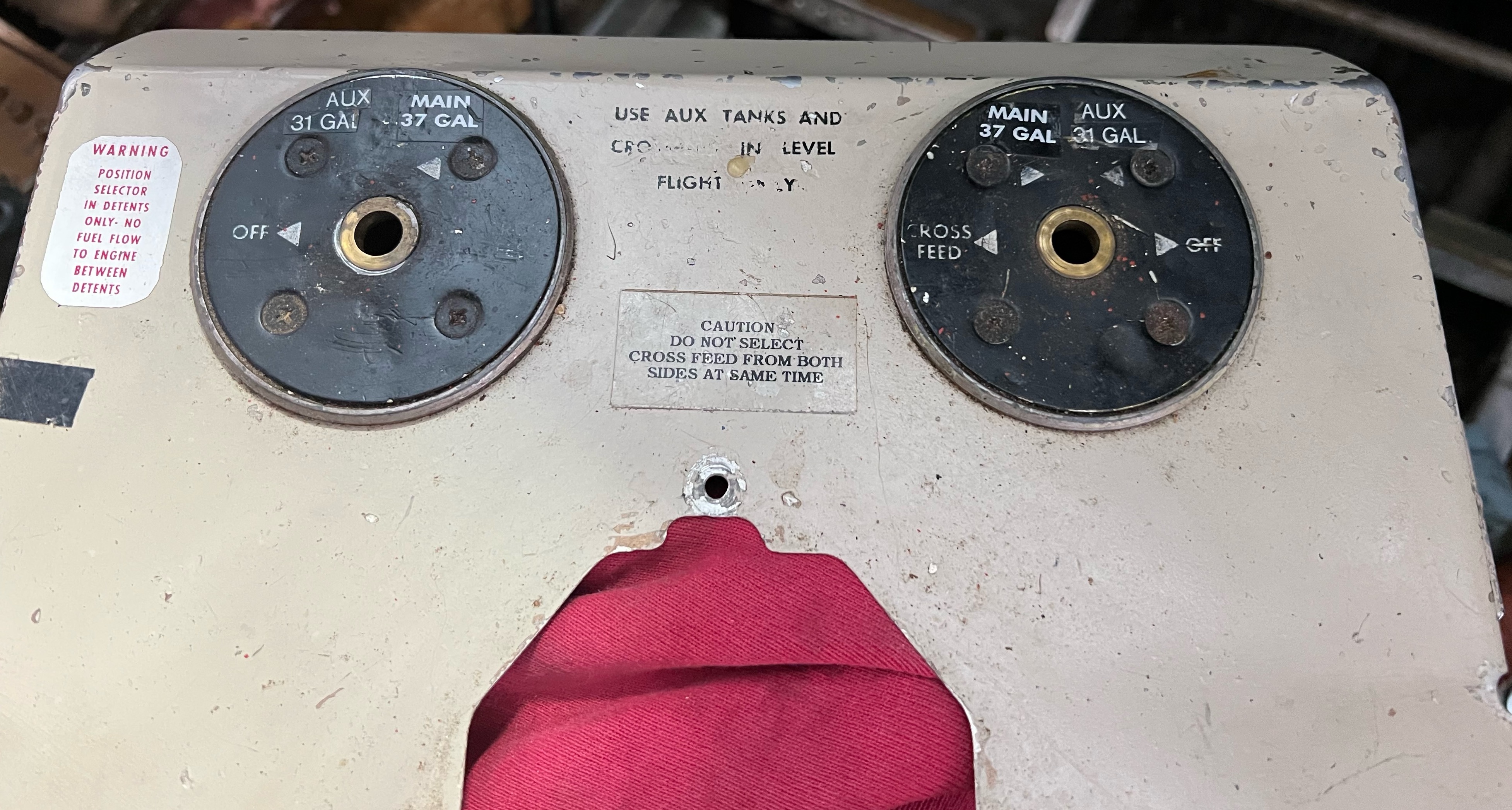
Baron 55
Fuel Selector Cover Placard Makeover
~TC-191 THRU
TC-1607
TE-1 THRU
TE-942 (Except TE-938)
Since you've made it this far in the B55 Fuel
Selector Valve narrative, you might be interested in buying an extremely custom
set of placards to freshen up your fuel selector cover panel.
If you're diving into your fuel selector
valves for o-ring replacements and your 50 year old cover plate has seen better
days, you might like to give it a fresh look.
Check out the before and after pics of how my
custom placard design came out and click the PayPal Buy It Now Button if you'd
like a set:
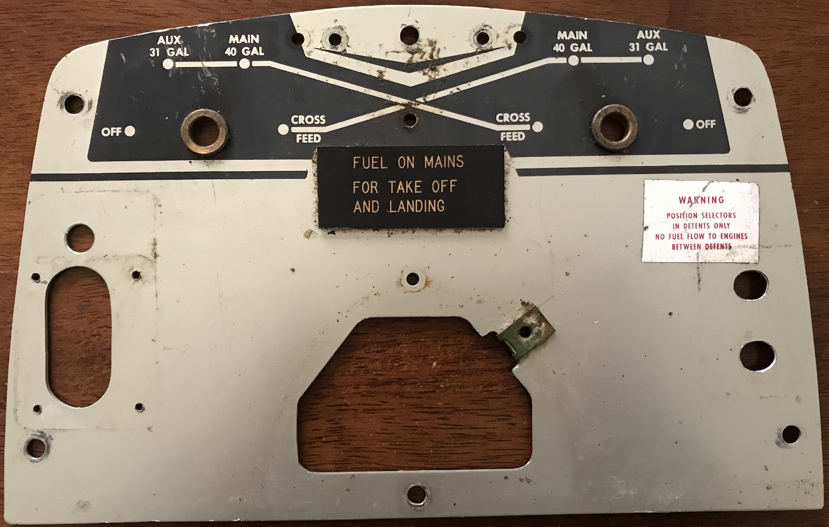
Before
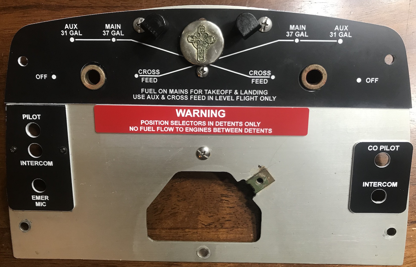
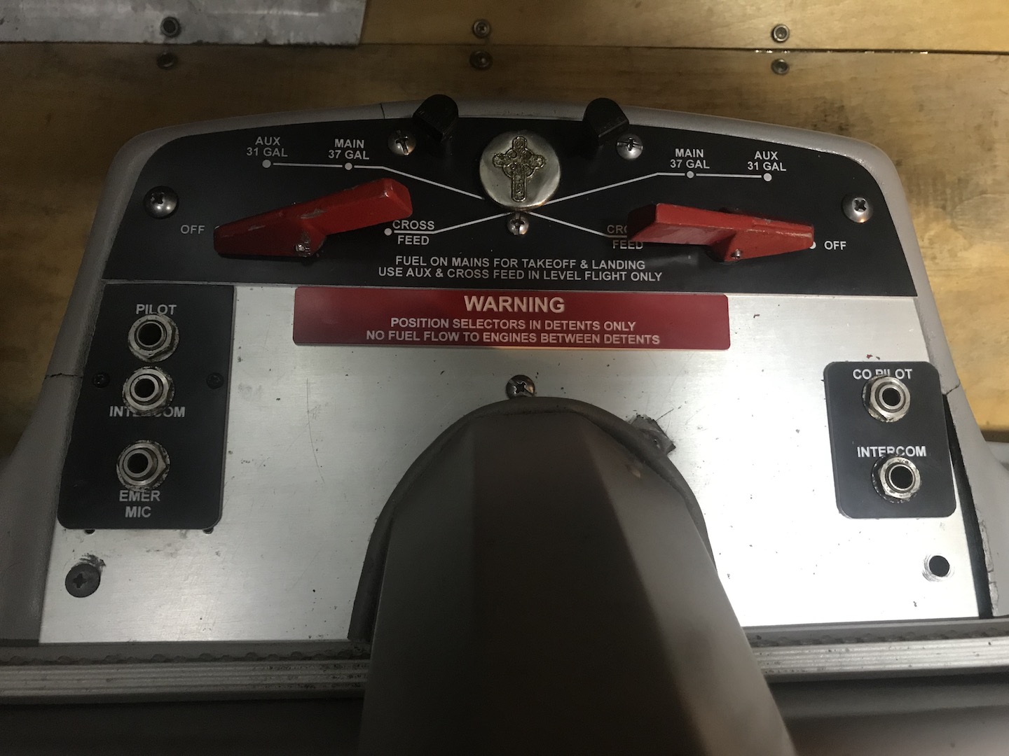
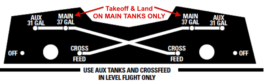
After Replacement Placards
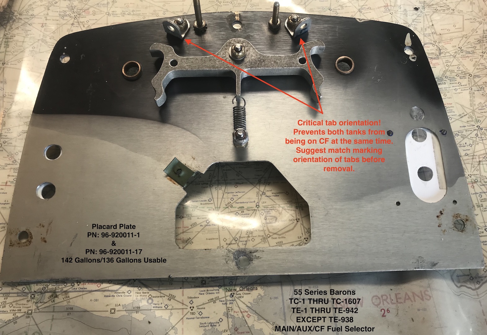
Cover Plate Backside View
For $95 (includes FREE USPS
Priority Mail US Shipping), you will receive the full width top main selector
valve roadmap placard and the red "WARNING" placard (as shown below) that sits below.
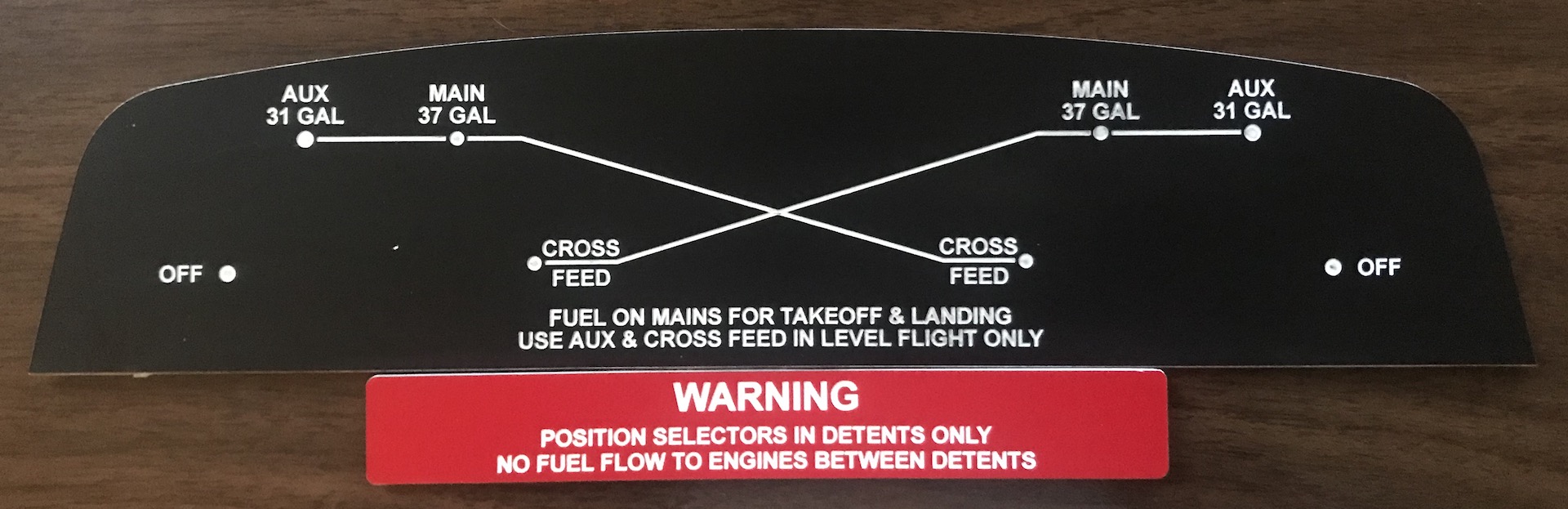
It does NOT include the
intercom placards since these may or may not be how your cover is configured for
your intercom setup.
The 37 gallon Main marking is
in compliance with the latest POH published limitations (all us 55-Series
drivers know it is a 40 gallon tank but 3 gallons became legally deemed unusable
in later years).
Applicable ONLY to the
following 142 Gallon/136 Gallon Usable SNs:
~TC-191 THRU
TC-1607
TE-1 THRU
TE-942 (Except TE-938)
NOTE: Using the existing cover
plate as a template, you will need to drill your own holes in the large main
placard to insure that the placard fits your exact fuel selector cover and any
post lights that are in your original cover. The large holes for the selector
valve shaft bushings are approximately 11/16" and are easily done with a step
drill like
THIS.
Your purchase also helps to
supports the CSOBeech.com site.
This placard will NOT fit Early 95-55 Models with a fuel selector as shown
below. It is believed that the 95-55 Aircraft are SN: TC-1 thru TC-190.
As always, if you have no idea what a fuel
selector or an O-ring
is or what a good one is supposed to look like or what a bad one looks like,
close this browser page and ask your A&P licensed mechanic to have a look at
your fuel selectors and let you know if they are leaking.
If
this narrative has helped you, please
donate to keep CSOBeech.com Free
|