And finished it with some plastic feet for the corners.
In laying out the components I wanted two things: 1) to be able to see the
meter from the cockpit when the supply sat on the left wing and, 2) to be able
to take off the lid without disconnecting wires. I could have done both by
mounting all the parts in the lid, but that was undesirable for a few reasons,
so I put everything in the base except for the fans, and just have two small
wires coming from the lid.
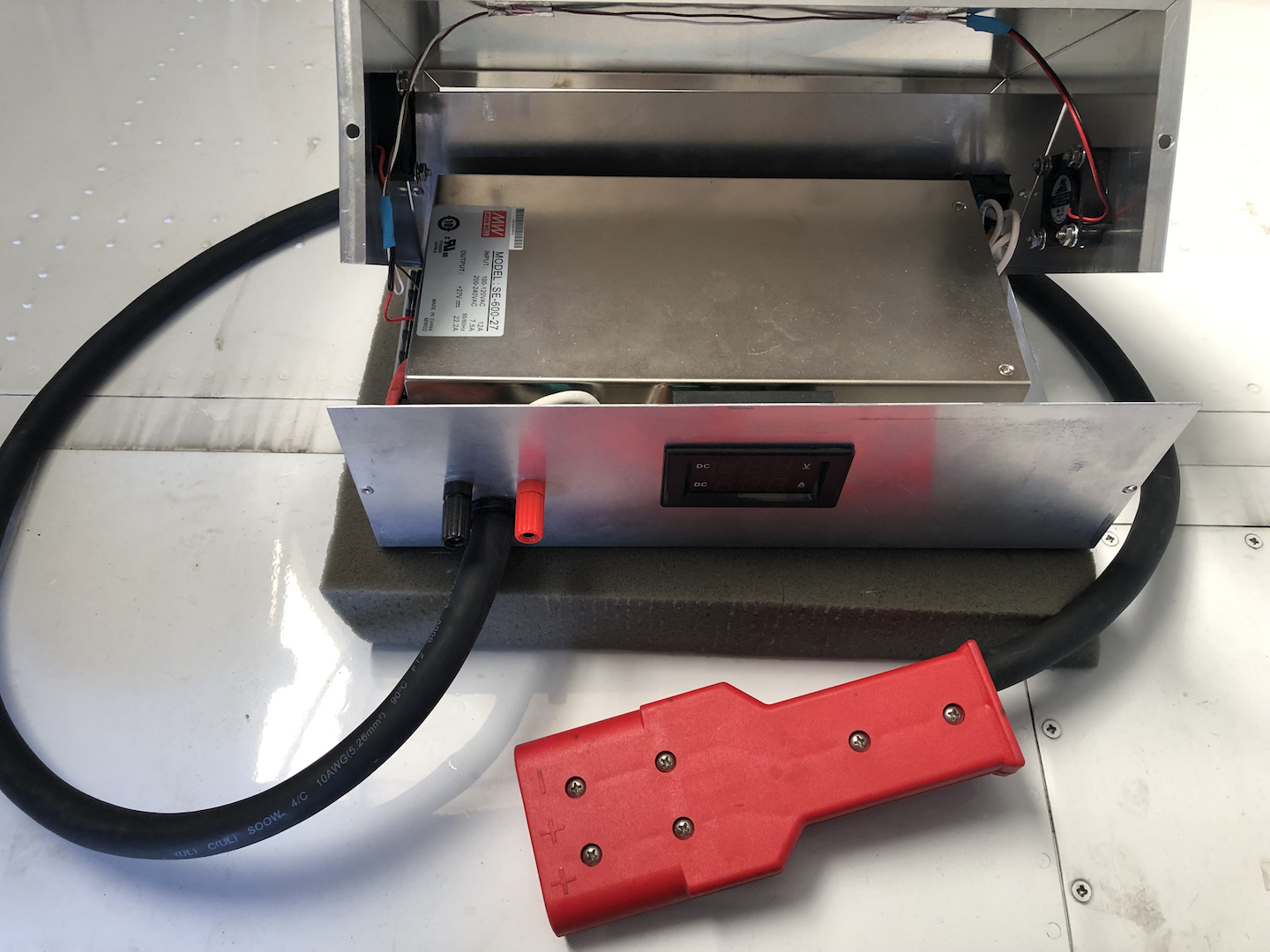
For now I have banana jack outputs where I ghetto clipped my jumper cables
with the 3-prong aux power plug, but the next Spruce order will have another
3-prong plug for use with permanent wires.
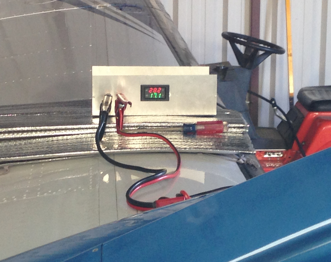
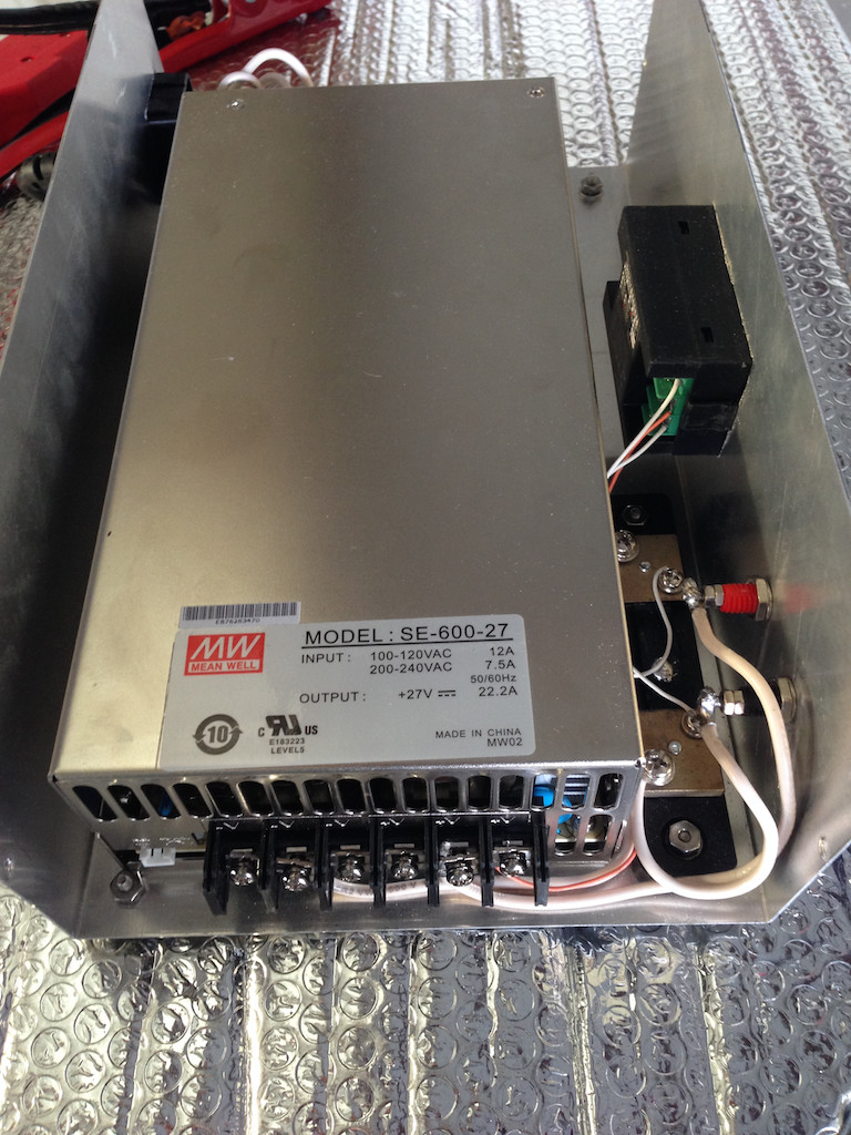
The supply shows 28.2V and the JPI shows 28.0V when drawing 10A, not a bad
start, and it will probably improve once I ditch the jumpers. The supply
actually has Kelvin pins to compensate for the drop, but it is not worth the
bother. With everything on--panel, avionics, lights, etc.--I draw about 19A and
the supply keeps up. I could probably swing a gear with that, if there is ever a
need.
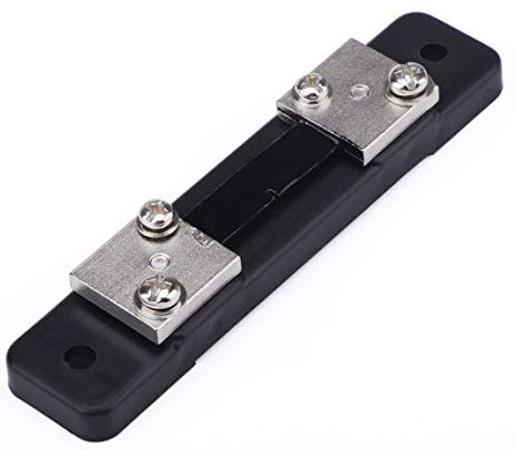
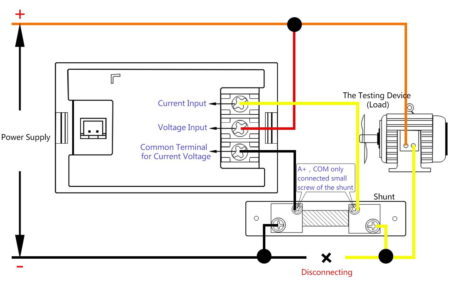
Here is how you would connect the panel meter
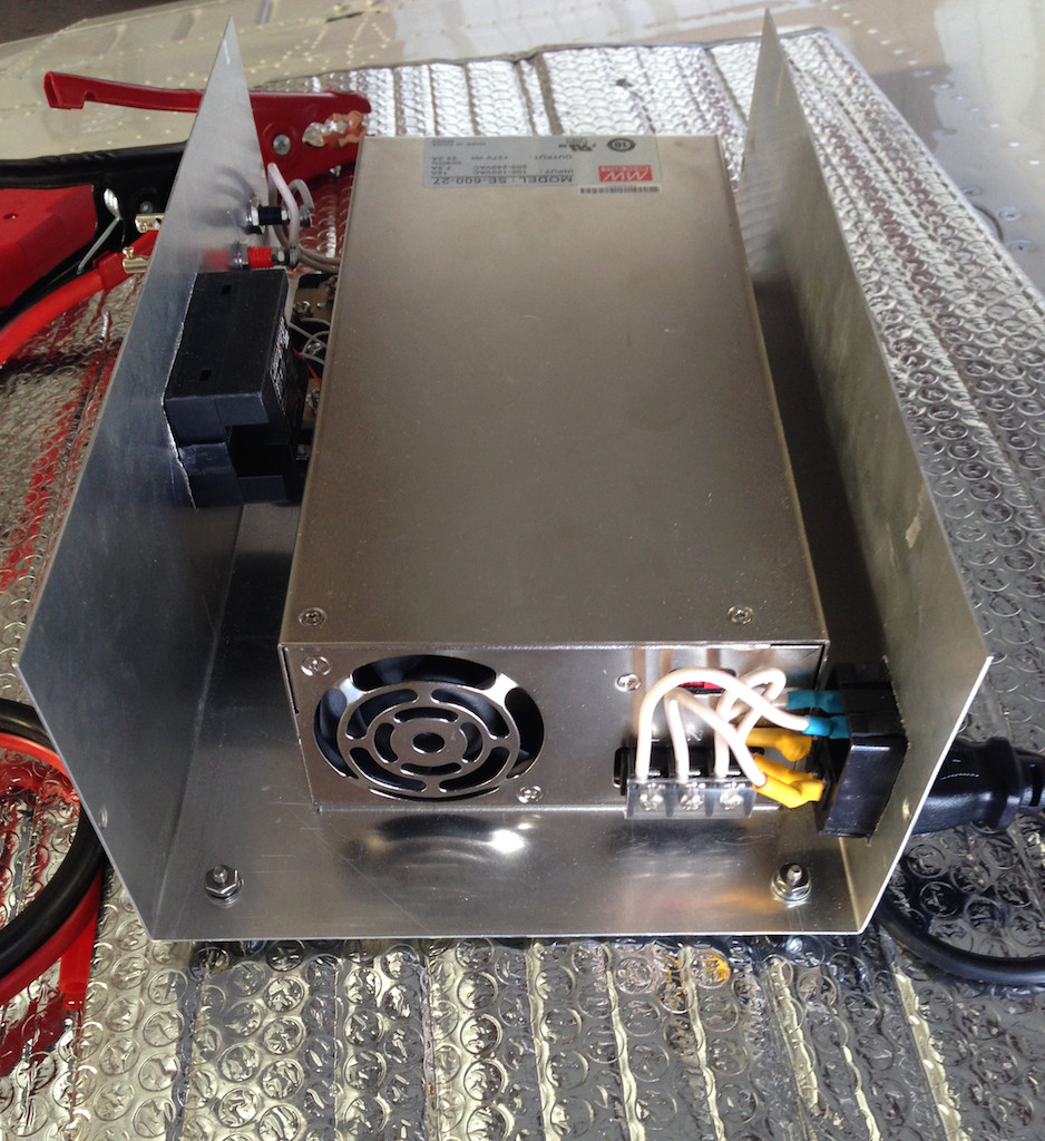
I could have built this supply for under $100 if I took some shortcuts or
scrounged parts, but all in it was still under $150 or so. Attached pix are the
results, taken with the lid off while I was testing it out.
The gauge wire for the internal hookup in those pix was 12 ga., however, as I
mentioned back then, that was the ghetto version where I was trying it for the
first time with the jumper cables clipped to the bananas. I have since added a
4x10ga cable to power the bus per the pix below, and paralleled two wires for
each pole, i.e., 2x10ga for (+) and 2x10ga for (-), which results in approx 4 ga.
for each. I kept the banana plugs in 12 ga. to power up non-bus stuff on
occasion.
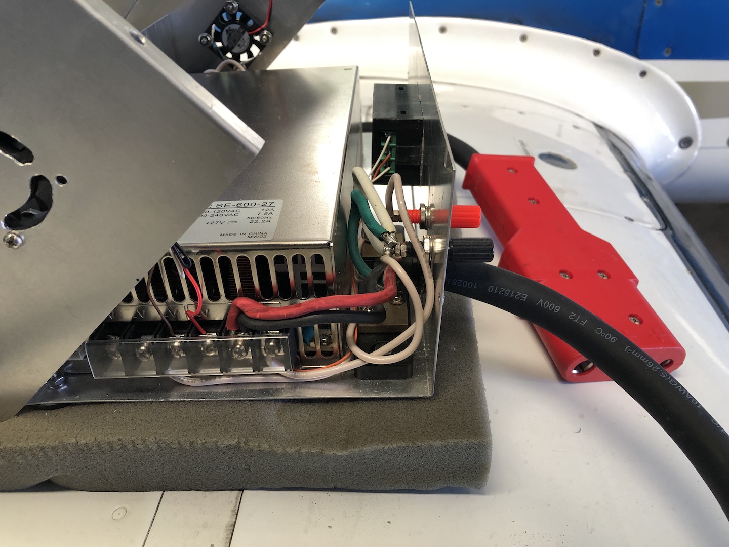
The cable length only needed to be a couple feet because my power port is in
the nacelle, but I theoretically made it long enough to reach the power port
while sitting on the nose of my hangar neighbor's F33. That function has yet to
be tested.
Now with the heavier cable directly connected to the supply, I get about 0.1V
drop when drawing 17A, and I suspect most of that is between the left nacelle
power port and the aircraft bus bar.
That 17A, incidentally, is with the avionics on along with all my lights,
which are a mix of LED and incandescent. This is the load I sized the supply
for, and it has proven to be quite capable. I am not sure I would swing a gear
with it, but I bet it could be done.