During EAA/OSH 2024 I was searching
for an ignition system upgrade for my B55 Baron. I had heard about some
of the improvements that several manufacturers had made in improving
upon the ubiquitous magneto, which has served piston GA engines well
for over half a century.
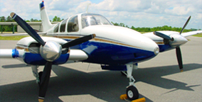
I was most impressed
with the Electroair STC'd system because, well, just look at the monster
ignition coil it employs in creating fire across the spark plug gap.
It's the size of a large brick and a bit heavier with ancestry from
automotive high energy ignition systems!
Electroair Ignition Coil
The other so-called electronic ignition systems
utilize a simpler and much smaller package that was about the same size
footprint as a conventional magneto, essentially creating an electronic
magneto. Whereas, I believe the Electroair system represents a TRUE
electronic ignition with it's monster coil creating 70,000 volts and a
duration of about 20° of crank rotation vs. ~12,000 volts and 5°
respectively for a conventional magneto, a
controller that advances ignition timing with altitude, a replacement
cockpit control panel that eliminates the old rotary magneto start
switches and reported gains in fuel efficiency and horsepower.
Electroair Switch Control Panel
Make
no mistake, this install is very extensive and labor intensive on a Baron (much less so on a Bonanza),
due to the coil mounting locations being limited to the nacelle cavities
and the fact that you are installing TWO systems! For economics, I highly recommend owner
assisting in all the tedious wire pulling and fabrication grunt work (as
I did under IA supervision for my install) as the way to get the lowest cost install
as well as tidy and precise workmanship that will satisfy you.
By no means is this narrative to be considered as the ONLY
way to install an Electroair ignition system in a 55-Series Baron, it
is however, the way that my IA and me chose to install it in accordance
with the Electroair Install Manual and published FAA repair and
maintenance practices in AC 43.13.
The STC'd kit is packaged extremely
well and nested in styrofoam compartments with a flash drive containing
all the install and STC documentation.
Electroair Ignition Reported Benefits
Once I committed to
the Electroair system my IA and I began the head scratching on how we
would approach the install of the components and wiring in a B55. My IA
had already done an Electroair install on his V35B Bonanza and a couple
other Bonanzas but hadn't done a Baron yet.
We phoned an IA friend, Michael Thompson of AVSTAR,
who had previous installation experience with an Electroair system in a
Baron. He told us what we already knew that there was no engine bay
real estate for the monster ignition coil and his install used the
engine nacelles for the mounting of the coils. Michael stated that his
install was on the forward facing bulkhead of the nacelles.
After this
conversation my IA and I looked at the nacelle cavities and realized
that there are outboard inspection panels that would allow anchoring of
the coils within the nacelle cavities while allowing for an easy
penetration access through the engine bay firewall into the engine bay
for the plug wires to reach their cylinders. We did not see a good way
to mount the coils in the outboard sections of the inspection panels and
besides, the left inspection panel opening had the ground power port
structure in the way. Additionally, we could not see a way to get the
six plug wires into the engine bay from
the outboard inspection cavities.
Entry to the nacelle cavities was made through a factory inspection panel in the top of my nacelles.
Sizing Up the Coil Mounting Space
We chose to tap the
coil mounting
plates that come in the kit to 5/16-24 and fitted
with AN5H-4A bolts then safety wired to secure the coils to their home
in the nacelles. This allowed a one-handed coil placement and install
inside the nacelle, while the other hand threaded the AN bolt into the
mounting plate.
One can also choose to simply use nut and bolt hardware to secure the coils to the nacelle sidewall.
Tapping the Coil Mounting Plate 5/16-24
Click to Enlarge Above Images
The
positioning of the coil for mounting position is critical since you have
to insure that you have adequate space within the top and bottom of the
cavity to install the top and bottom plug wires onto their respective
towers. My install kept the coil mounting plate parallel to the angle of
the riveted top reinforcing section. My measurements are pictured but
since these are handmade aircraft you would be wise to measure 3X and
drill once!
In order to mount the
right engine coil to the outboard side, two fuel hard lines had to be
removed and replaced with flexible lines from PHT in Tulsa.
With the coils mounted
we now focused our attention on the firewall penetration for the
ignition wires. Our plan was to cut a 2.125" hole in the firewall in
conjunction with a 2.5" sheet metal disc with six (6) 0.50" holes for
the plug wires that will be fitted through 0.50" OD Tygon tubing for
chafe and cross fire protection.
After another bout of
head scratching my IA and I selected the firewall penetration location
for the 2.125" hole to be the area aft of the mixture arm on the
throttle body. This allowed angle drill tool access to create the hole
and hand working space to manipulate the plug wires and secure the tygon
tubing with wire ties.
Both Electroair and my IA recommended that
the Electroair system be connected to the lower plugs since the lower
plugs tend to foul more easily and the high energy of the EIS can manage
minimizing that fouling. I'm all for anything that reduces the amount
of times I have to remove the bottom plugs in my Baron for cleaning!
The plug wires were
mounted to the coil towers in accordance with the provided instruction
manual (pay particular attention to the Continental diagram in the
instructions) and cut at their cylinder lengths (with some added service
loop) and then terminated with the provided hardware.
Based on the RE coil
location and firewall penetration location the supplied lengths of wire
made the following RE wire combinations: 6 + 1, 5 + 3 and 2 + 4.
Based on the LE coil
location and firewall penetration location and supplied lengths of wire,
we were only able to make cylinder 2 + 1 out of one wire leaving us
with only 2 wires in the original kit to fit up 4 cylinders. As a result, we requested and received two additional plug wire lengths for our Baron installation.
To protect the plug
wires from exhaust pipe exposure they were routed inboard of the engine
mount utilizing 8mm plug wire separators to keep things tidy.
The below image is an example of what NOT
to do with your Electroair ignition wires. Bundling them close together
without spacing can wreak havoc in crossfire at high altitudes. Air
acts as an insulator, thinner air is LESS of an insulator!
Below are a couple videos on spark plug wire assembly & Routing
We chose to mount the
Electroair Magneto Timing Housing (MTH) in the left magneto position of
both engines. This choice left the conventional right magneto to fire
all the top plugs. Be sure to do your MTH timing procedure per the
Electroair install instructions and use the #1 cylinder for determining
your TDC position! Also, the magneto hold down ears may need to be trimmed to fit the MTH profile.
My IA had success
shortening his remaining magneto wires on his V35B and reinstalling the
spring "stingers" but I wasn't as fortunate.
I'd recommend using the existing "unmolested" harness and just
spreading the additional wire out in the top of the engine and
cylinders.
The next pair of
components to be mounted were the electronic controllers. We chose to
mount the controllers on the nose baggage aft wall on top of the heat
duct channel using rivnuts which also allow for airframe grounding
points for the wiring harness coming into the controllers.
Now comes the tedious part - the pulling of the wiring harnesses through the airframe to their respective homes .
NOTE: Upon
examining the supplied length of wiring harness for the controllers to
the coils and MTHs, we requested an additional 6' length for the RE and
8' for the LE. This turned out to be more than adequate and gave, what
my IA called, a comfortable service loop that we coiled in the baggage
compartment.
We started at the
controller and pulled the four-pin connector for the coil (with red
power wire) and the MTH harness up through the top of the nose baggage
and into the back of the instrument panel and then down to the leading
edge of the wing where the engine control cables exit and then up into
the engine bay. The RE had an unused grommeted access hole in the
firewall that was used for the coil wires. The LE used the center hole
of the coil wire disc to make entry of the wires through the firewall.
It's a good idea to use appropriate chafe protection where the wiring
passes across the sheet metal openings.
Engine monitor wiring makes for tight quarters in the leading edges .
RE Wiring To Engine Bay
LE Wiring To Engine Bay
After pulling the coil
and MTH wiring to their respective positions in the engine bays, I
moved to pulling the control switch wiring, LE and RE, into the cabin to
the pilot's side, exiting at the OE position for the magneto switches
that are mounted into the OE escutcheon.
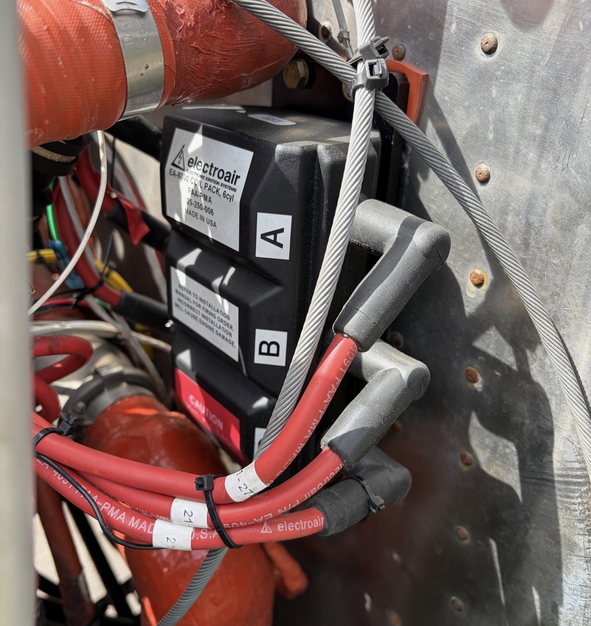
After removing the
magneto switches we were left with this huge nest of wires likely due to
a previously removed Shower of Sparks system .
Fortunately, my IA is
also an ace avionics and electrical guru. The provided Electroair
control panels required identifying the magneto P-leads, grounds, bus
voltage when the master key switch is turned on and starter relay wiring.
The starter button connection screws were worthy of a watchmaker! Thankfully, this was no big deal for my IA's wiring skills.
NOTE: During my IA's wire sleuthing we discovered that my SN starter relay hot wire was an UNPROTECTED
wire (J1A18 and J2A18) direct from the bus. The wiring diagram calls out this unprotected wire to be in SNs prior to TE -329 and prior to TC-1029. This is confirmed with the factory wiring
diagram (see below), which showed the later SN aircraft starter relay hot
wire (J1A18) routed through the Cabin Lights 5 amp CB. My IA was happy to correct this and
route the starter relay hot wire through a 5 amp CB.
Each Electroair system requires a 2 amp CB for each controller and a 10 amp CB for each coil (this should give you .
Power for the CB panel
was taken from the bus side of the Master Relay which is located in the
aft right corner of the nose baggage compartment.
We chose to make a CB
mounting panel for mounting in the nose baggage. My IA's preference
was to have the CBs inaccessible in flight, preferring to have any CB
tripping resolved on the ground. Additionally, the wire length from the
Master Relay (in the right side rear corner of the nose baggage) to the
CB panel was a short run. Your IA's CB location preference may
vary.
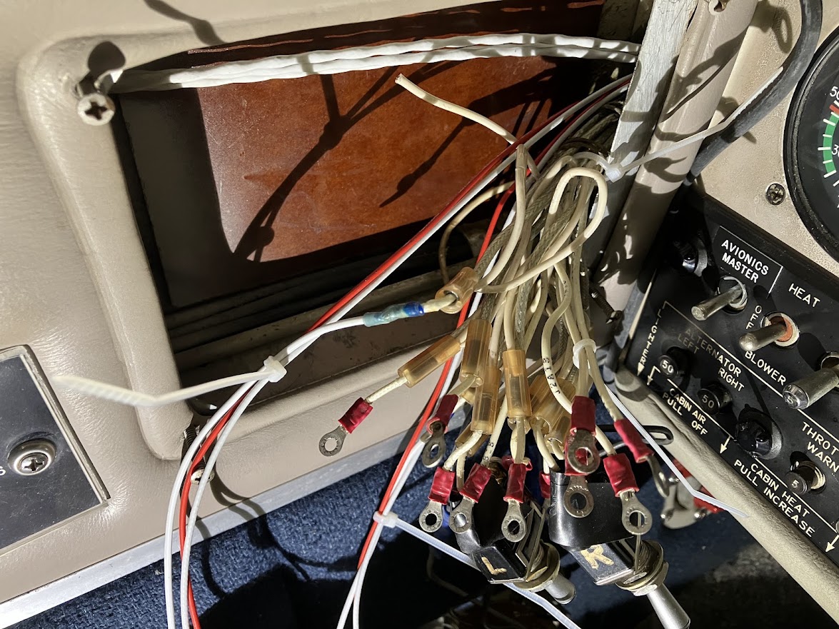
Below is the
dimensional sketch I made to create my sheet metal replacement control
panel mounting plate. It will soon be replaced by a 3D printed panel
with 0.375" thickness that will create the offset from the left outside panel
that the factory escutcheon incorporated. Click HERE for the 3D printing .stl file.
The next pair of
connections involved the 1/8" ID hose to feed engine MP info to the
controllers for timing advance per Electroair's advance curve. It was
found that there was enough play in the MP instrument hard lines to
place the necessary "T" in the line to tap into MP info.
The below fittings info is courtesy of Electroair research. I employed Option #1:
Option#1:
Simplest
way to tee into the MAP line is at the gauge itself. The nipples that
are on the gauge will need to be replaced with p/n AN826-4D. This
fitting will have an 1/8"NPT on one leg and 1/4" flared tube ends on the
other leg.
From
the tee, I would reduce one of the 1/4" flared tube ends with p/n
AN894D4-2. Then come off the #2 end with flexible vacuum line like
Aeroquip 306-2 and a 471-2D on one end; the other end will slip on to
the fitting on the controller.
B.O.M.
AN826-4D (MS20826-4D) 2ea
AN894D4-2 2ea
471-2D (or 311-2D or MS27404-2D or AN773) 2ea (Univair)
306-2 (or 193-2) length necessary to go to controller
small hose clamp 2ea
Option #2:
Again,
assuming the thread into the gauge is 1/8" female NPT, come off of the
guage with 1/8" NPT Nipple (AN911-1D). Attach an AN917-1D to the nipple.
Off of one end of the tee, attached AN816-4D nipple (this will attach
to the supply line from the engine). On the other leg, use AN816-2D
nipple and then attach the flexible hose to the AN816-2D like above and
route to the controllers. A little more cumbersome than Option #1, but I
prefer pipe threads for insuring a good seal.
B.O.M.
AN911-1D 2ea
AN917-1D 2ea
AN816-4D 2ea (nipple for the hard line in the aircraft)
AN816-2D 2ea (nipple for the flex line to the controller)
471-2D (or 311-2D) 2ea
306-2 (or 193-2) length necessary to go to controller
small hose clamp 2ea
Final installation pics:
As
of this writing (28 February 2025), I have only done ground checks and
relatively short flight checks, one at 10,500' and a short fuel run for
$4.55/gal gas at KXBP.
Initial System Observations
Incredibly intense install labor component for twin-engine (owner assisted install is highly recommended for best economics).
Cold starting and hot starting are indistinguishable. Cold start priming and starting SOP achieves easy hot starts.
Seat of the pants takeoff power feels stronger
At
21gph, only one cylinder, RE #2 cylinder hit my 380°F action temp,
whereupon, the mixture was leaned to 20gph. This was likely due to the
more complete combustion of the fuel, the consequence of which is
creating additional heat (DUH). Extended long distance flights will be
needed to make an assessment on fuel savings potential.
Your
most cost effective install would be Owner Assisted with you doing the
majority of the grunt work under A&P supervision. However, if that
is not within your time or skill wheelhouse, click HERE for Electroair's list of experienced installers.
Below are videos of the initial short flight test at 10,500' leaned to 21gph (183KTAS) and 20gph (174KTAS).


