Bi-Color
LED for Auxiliary Landing Gear Light Indication & G5 Install
Bi-Color LED (Red/Green)
Auxiliary Panel Indication of
Gear Lights
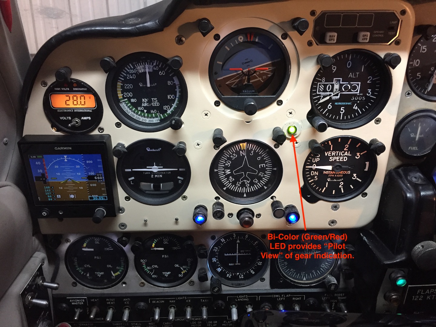
If you find it difficult to see your gear lights
over on the co-pilot side and have yearned for an "in your face" gear light
solution, or are doing a panel makeover and would love to add an auxiliary gear
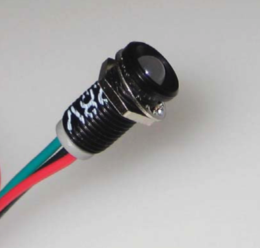
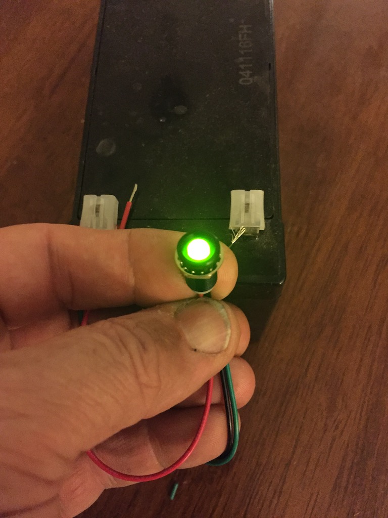
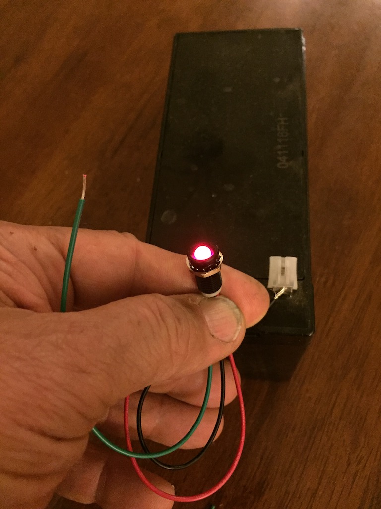
light indication, this could be the ticket for your panel. The above is a
bi-color LED that will react to the power feed that your existing factory gear
lights receive. Obligatory Warning/Disclaimer: This
bulb is NOT an FAA/PMA approved component. Nothing in this page supersedes your
responsibility, along with your licensed A&P mechanic as to the airworthiness of
your selected parts for your certified aircraft.
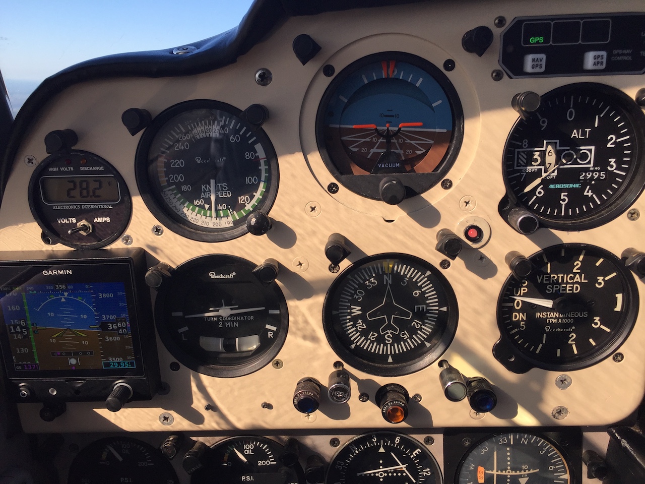
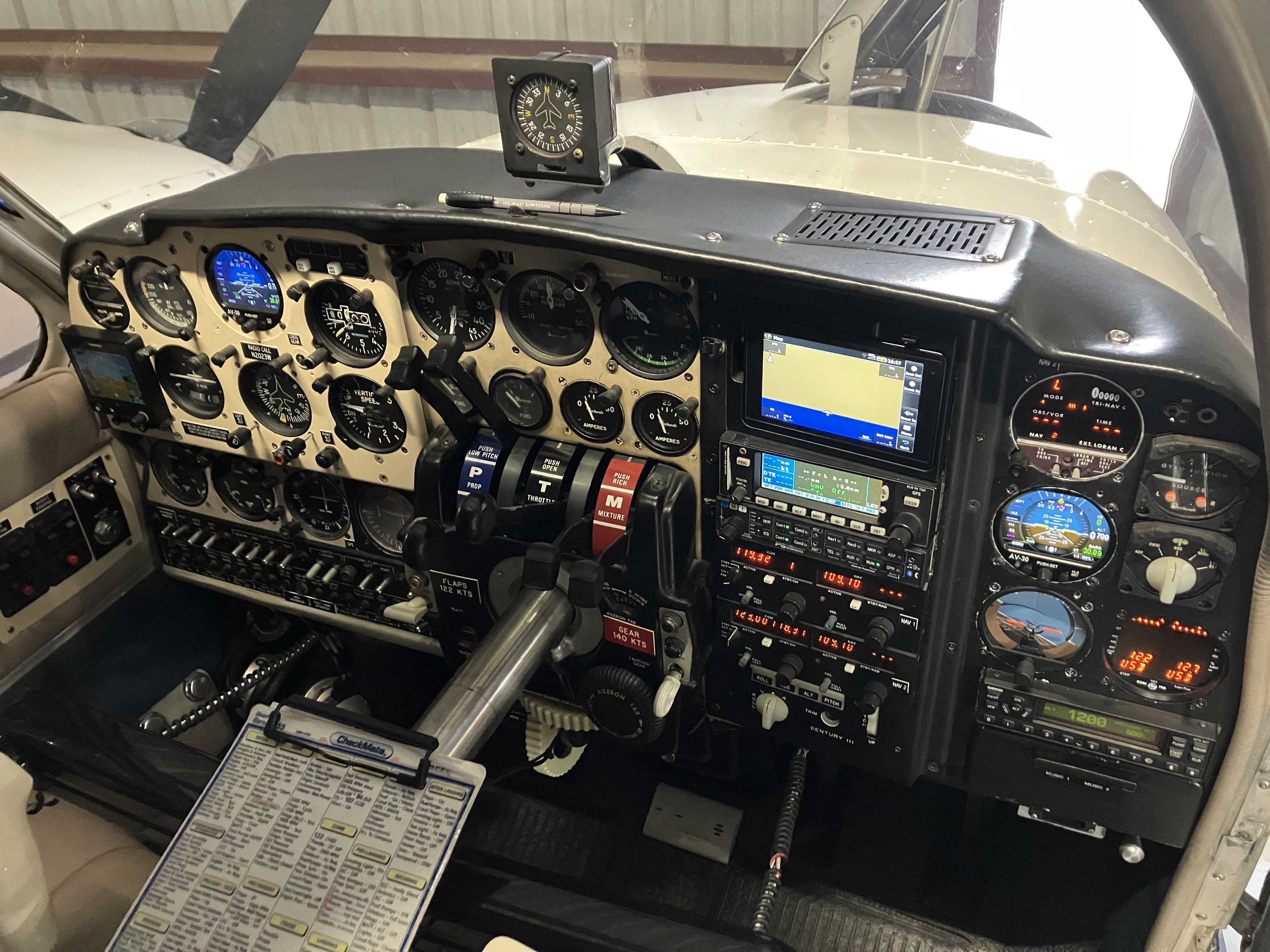
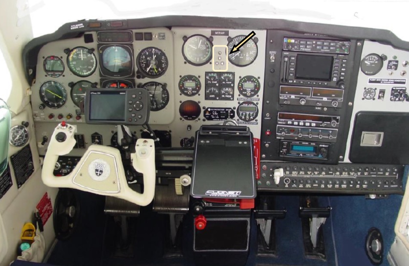
Below is my most recent 2020 B55 panel. The Bi-Color LED is mounted at about the 11 o'clock position to the VSI.
PS:
I use LED bulbs in all my post light and indicator light positions
which reduces the heat load on the ancient wire wound resistors Beech
installed for dimming.
HERE
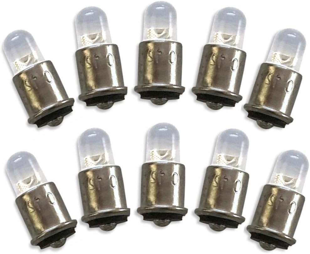
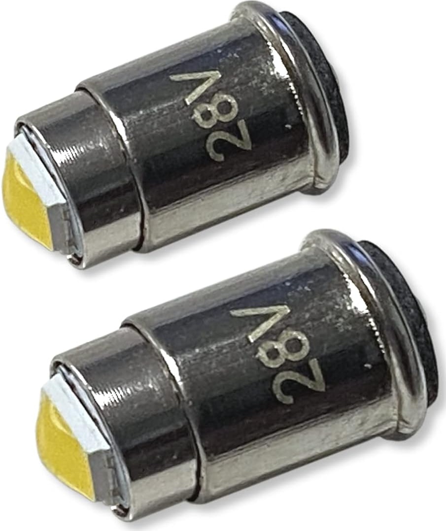
is a link to the #327 / 28V LED Bulbs (shown below) in a 10-pack that are Bi-Polar
and dimmable which means they will work in some indicator sockets that
are wired with the center post as the negative/ground.
HERE is a link to the #330 / 12V LED Bulbs in a
10-pack that are Bi-Polar and dimmable which means they will work in some indicator
sockets that are wired with the center post as the negative/ground.
HERE is a link to the #327 / 28V LED Bulb (shown below) in a 2-pack that are dimmable.
Continue reading below for a link to purchase the Bi-Color LED Bulb.
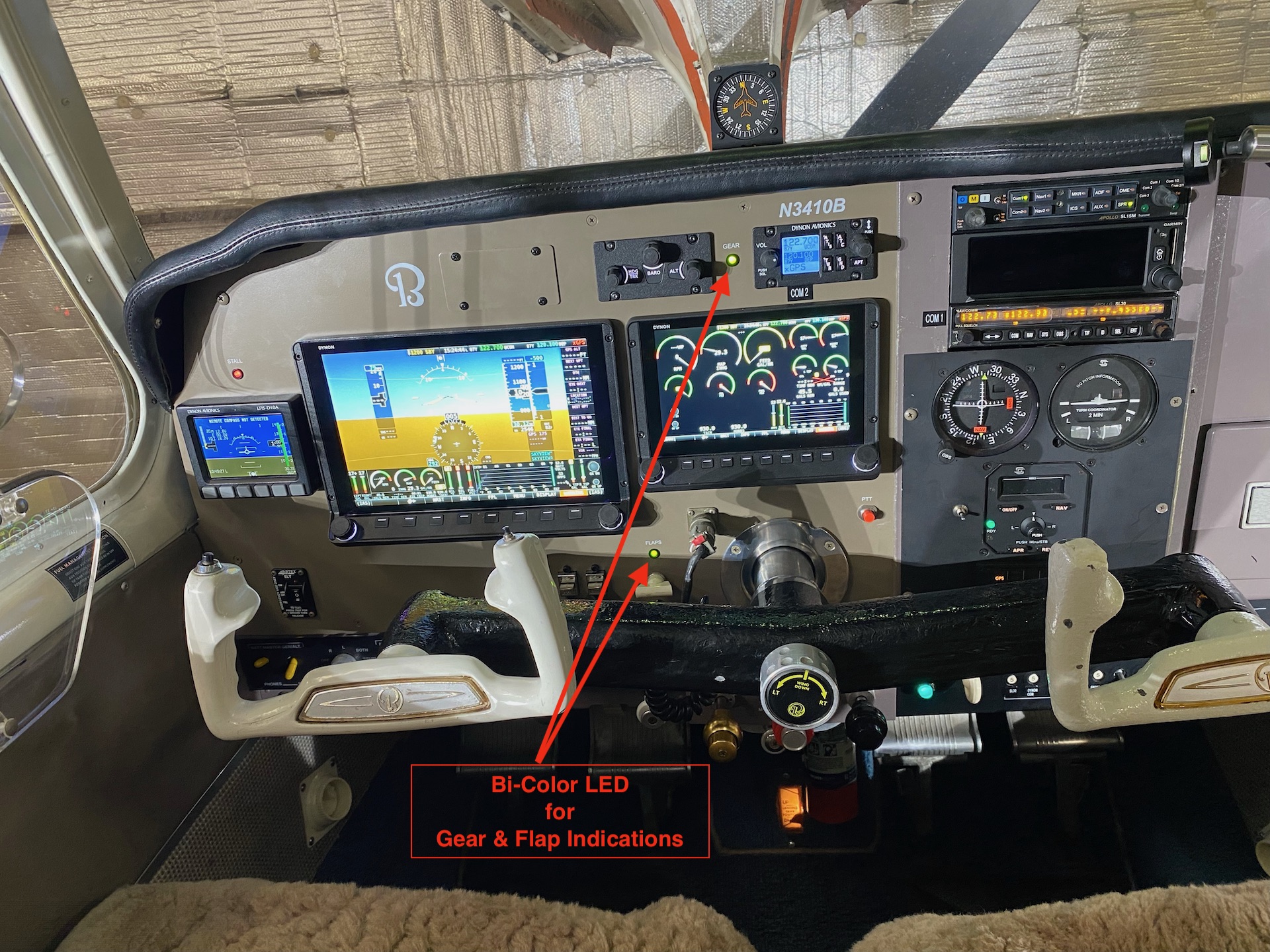
Below is a Bonanza Panel Makeover w/Flap and Gear Indications using Bi-Color LED
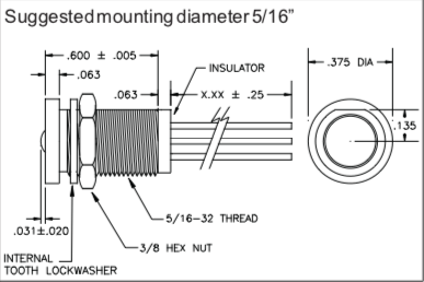
Simple one hole (0.313" diameter) install into
the panel, fed by the Green and Red power wires of the existing gear
lights and a simple ground connection. One bulb with two indications! How cool
is that?
The proper wires that feed the factory gear
lights can be identified by looking in your Beechcraft Shop Manual wiring
diagram section. The wire ID numbers can be found in the bundle leading to the
gear switch and can be seen by an agile person equipped with an LED headlight
laying on their back with their head under the co-pilot panel. An appropriate
tap into those wires and fed to the red and green sides of the bi-color bulb
will result in an auxiliary gear light indication in a place of your choosing.
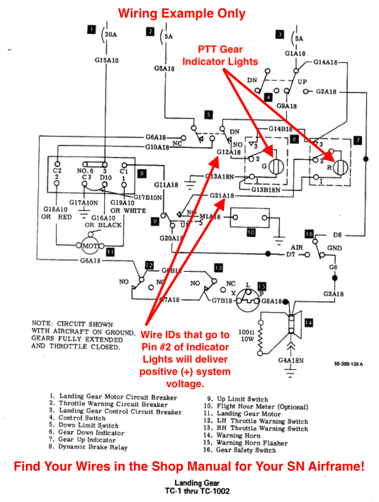
My B55 wiring diagram is shown below as an
example of what to look for in YOUR SHOP MANUAL FOR YOUR SN.
Below is an example of a Bonanza landing gear
wiring diagram - Remember, you must look up the wiring diagram for your specific
SN to properly determine how to make your connections. The wiring diagram below
does NOT apply to all Bonanza SNs.
In the above wiring diagram you can see that the Red and Green lights
are fed CONSTANT POWER positive voltage through the LG motor CB. So, this would mean that the circuit for each light is GROUND
activated.
I have recently learned that this
Bi-Color LED is NOT bi-polar. Meaning that it will not light with a GROUND
triggering connection to the red and green wires.
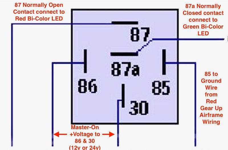
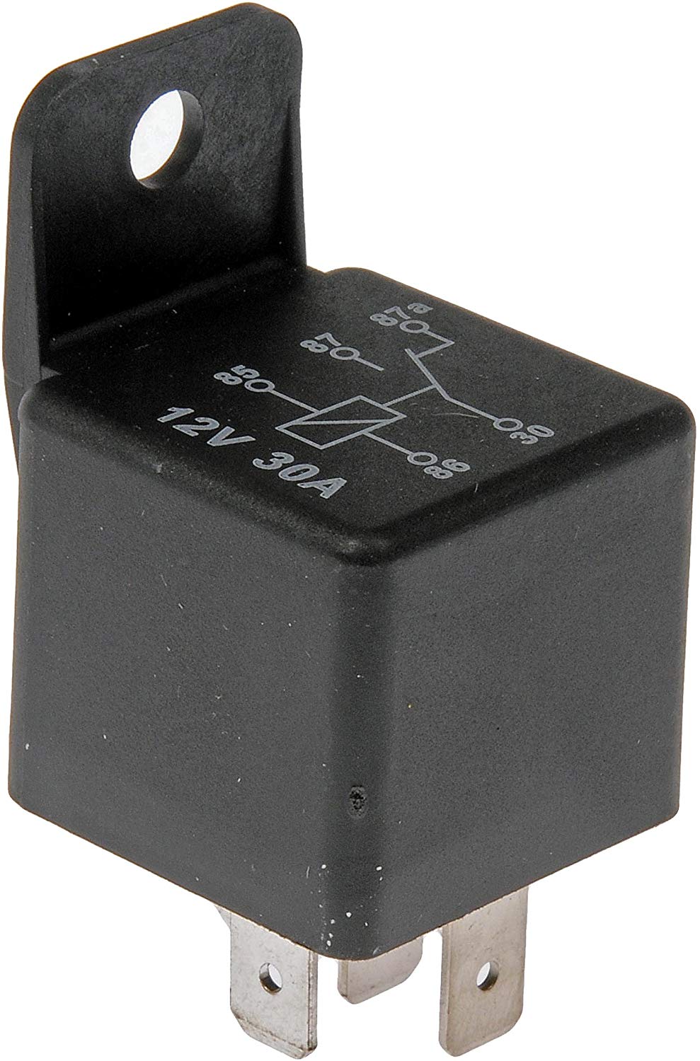
So, if your gear light circuit is of the GROUND
triggering type one would need to consider using an appropriate 5-pin
voltage relay to accomplish the Green and Red light triggering. A suggested
wiring for the relay might look like this:
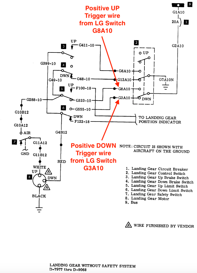
Here is another Bonanza wiring diagram example
for the SNs: D-7977 thru D-9068 (w/o Safety System) in which the positive (+)
trigger wires for the red and green of the Bi-Color LED can be tapped.
REMEMBER: Use YOUR SN Wiring diagram to determine the
trigger wires for the Bi-Color LED connections.
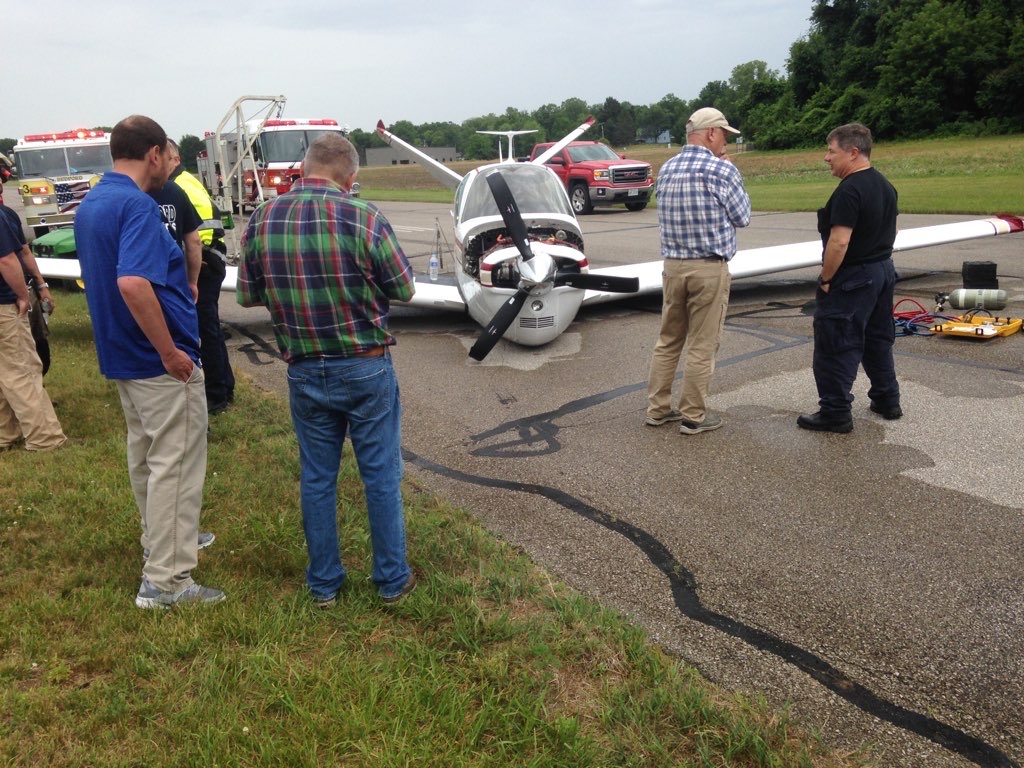
Maybe This Bonanza Driver Forgot To Look At His Indicator?
As with all things in this realm of modification,
consult your IA/A&P before proceeding with tapping into your factory gear
indicator wiring to add this auxiliary indicator. Some IA/A&P's may simply view
this as a logbook entry minor modification and others may not entertain it at
all. Your A&P/IA will fill you in on his
view.
These Bi-Color LED bulbs are available in 12V and 28V versions.
If you are seeking a better visibility solution
for your gear indication lights in your Beechcraft, please click the Buy It Now Button below
for the voltage unit corresponding to your airframe. Your purchase supports the
time and maintenance of the
CSOBeech.com site.
Purchase Price includes FREE USPS First Class Mail
Shipping for US addresses. International Purchases will be shipped
1st class US Postal International Mail.
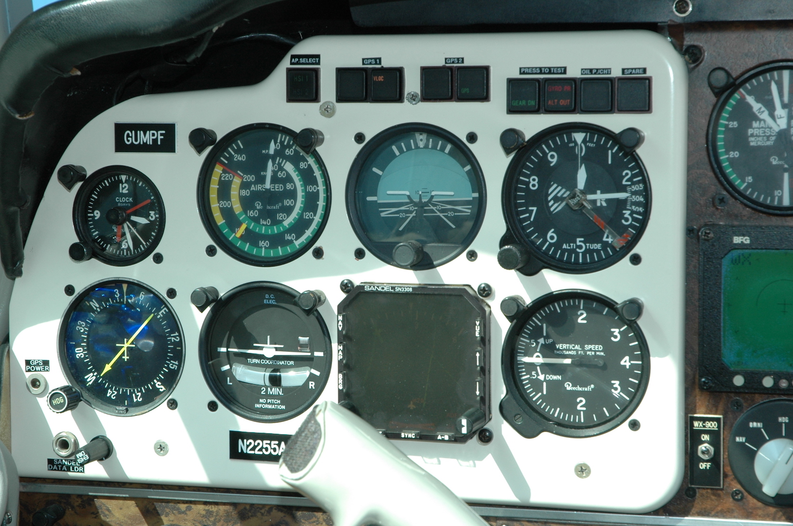
Above is an image of
what Dr. Dave Rogers did for a better (remote) gear indication plus a number of other
functions, e.g., HSI1/2, Alt out, GPS indications, oil pressure/CHT.
The annunciation indicators are all Eaton brand. They can have 1, 2 or 4 indication on a
single display. They also come as switches with/without press to test as shown.
Click HERE for the complete
history of Dr. Rogers Bonanza panel evolution and his sources for the Eaton
annunciators.
Below is another landing gear indicator light relocation idea:
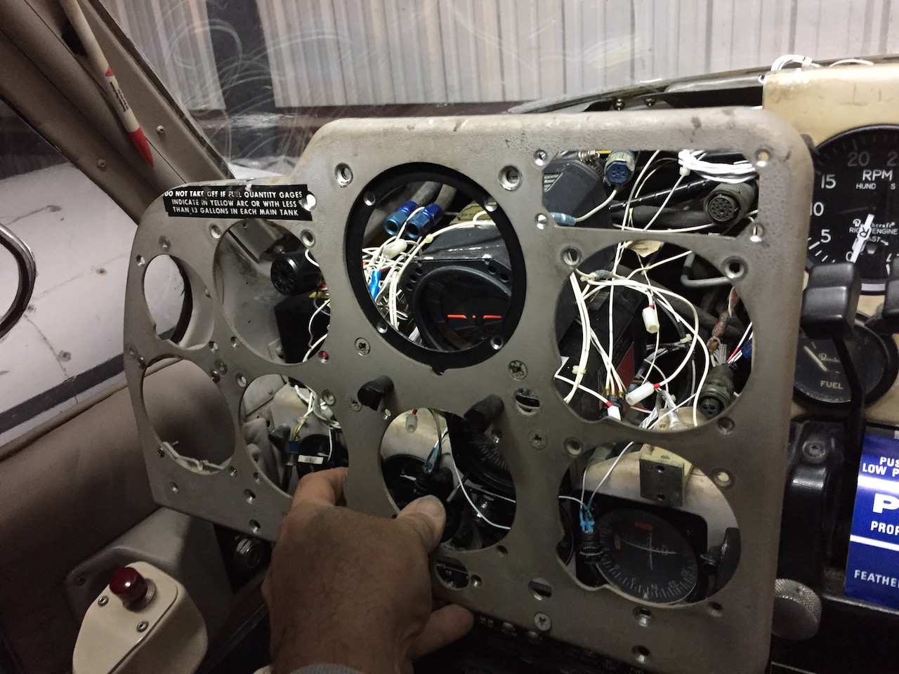
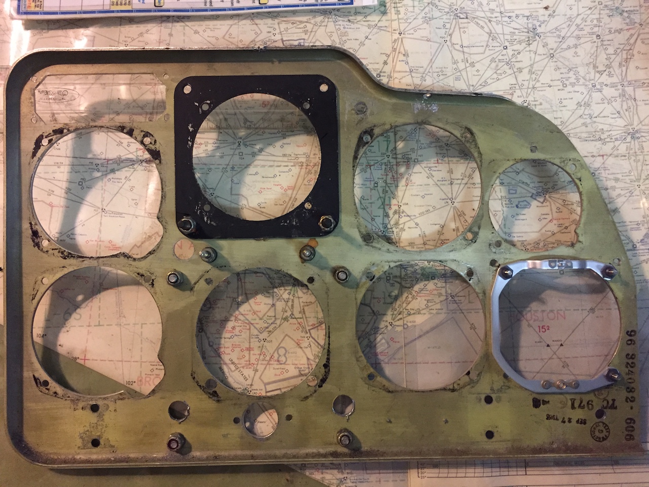
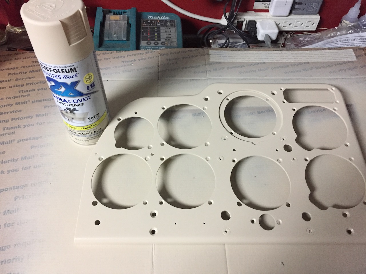
G5 Install Pirep
Here are more pics of a G5 install and floating
panel refinish project. Note to others, building a ship in a bottle would have
been easier, so when you get an eye popping install quote for a G5 install, know
that it is very tedious and time consuming work that requires patience and focus
to accomplish neatly and correctly. The post light wiring spaghetti was
maddening but I tamed the beast with some rewiring and reorganized routings.
Work such as this requires an A&P or A&P supervision of
your work.
Re-plumbing the pitot and static instruments was
essential since the 50 year old instrument hoses had given every measure of
service they could be expected to deliver. This too required very tedious
planning and execution in the tight space behind the panel.
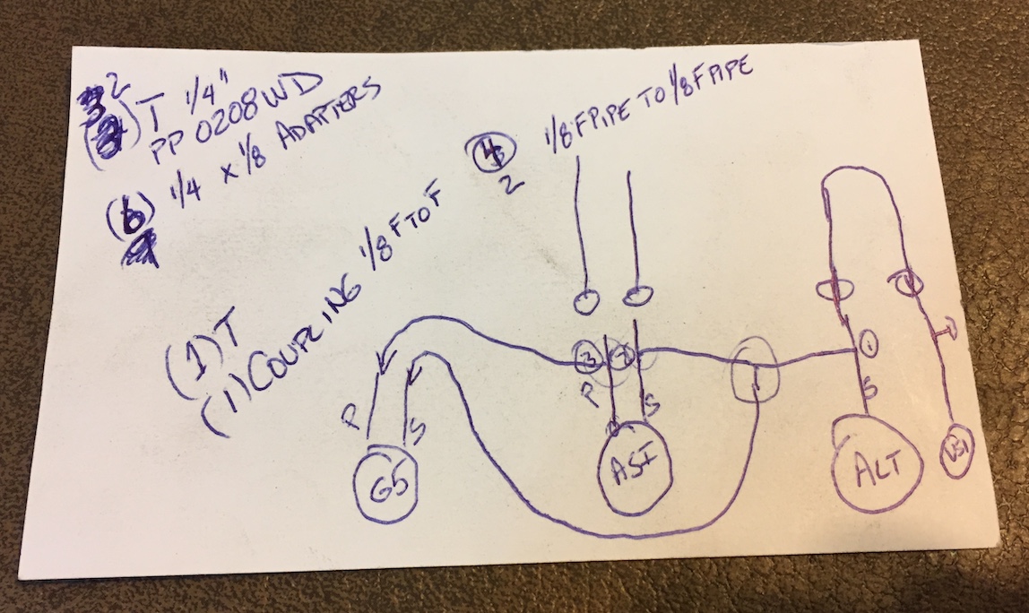
Below is the routing diagram that I created to
insure that all went back together correctly. It took five "T" fittings to
accomplish the hose routings.
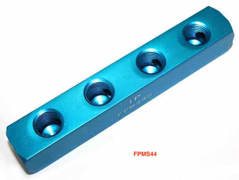
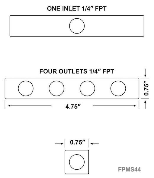
In retrospect a manifold fitting (PN: FPM44S)
could have been employed to make this plumbing addition much simpler for the numerous
static connections
.
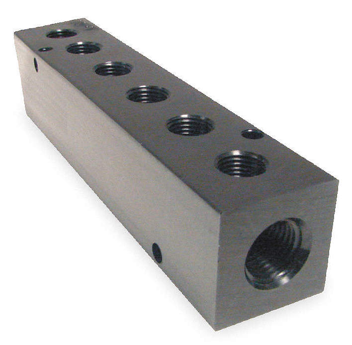
Or if you need a 1/8 NPT manifold,
HERE below
is a 6-port suggestion from Grainger.
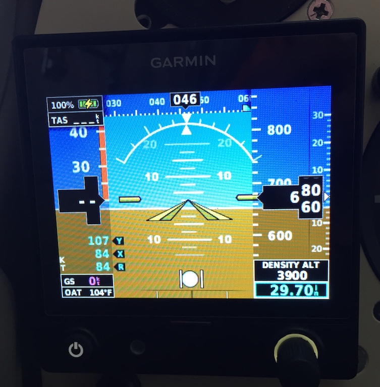
A GAD13 module was later added to the nose shelf,
where the magnetometer is mounted, and the lower cost Davtron probe kit was
purchased from Gulf Coast Avionics. The GAD13 allows the G5 to display OAT, KTAS,
Density Altitude and a Wind Vector on the HSI page. The Davtron probe mounting
drawing is HERE.
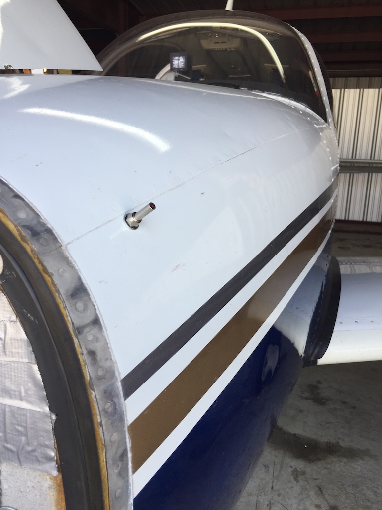
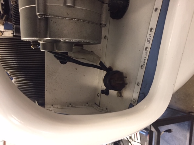
The probe location was chosen for it's decent
proximity to the GAD13 module in the nose shelf and the location mimics, albeit
a little forward, the factory pilot side OAT probe location on the side of the
fuselage. This location also allows for nose cone removal without having to deal
with another set of wires to disconnect.
Below are OAT probe locations showing the factory
Bonanza mounting location and a seemingly successful Insight G2 OAT probe
location in the inlet air duct slightly aft of the alternator. Bob S., II
reports that this inlet air location "always seems to indicate within 1/2°F or
so of the probe under the storm window."
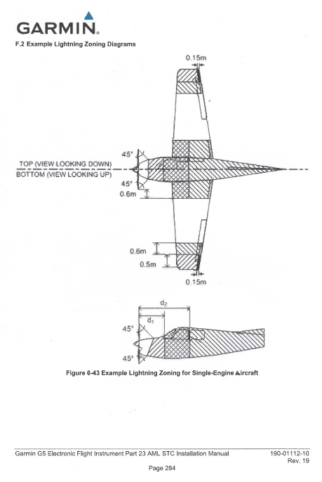
The below image from the Garmin G5 install manual shows the preferred single engine OAT probe location as the UN-shaded areas.
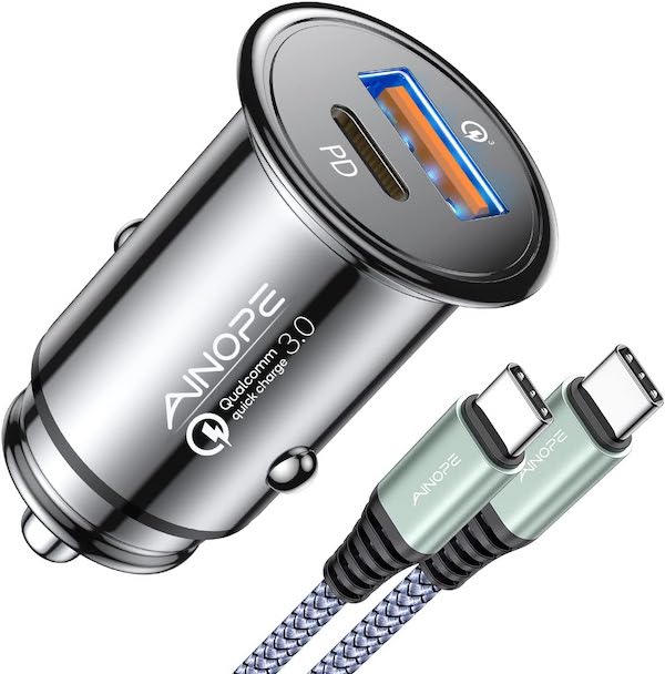
*With this powerful USB charger, I
don't worry anymore about using up my iPad battery on long flights with
my iPad constantly running my EFB w/ADS-B In WX & Traffic and chart
availability.
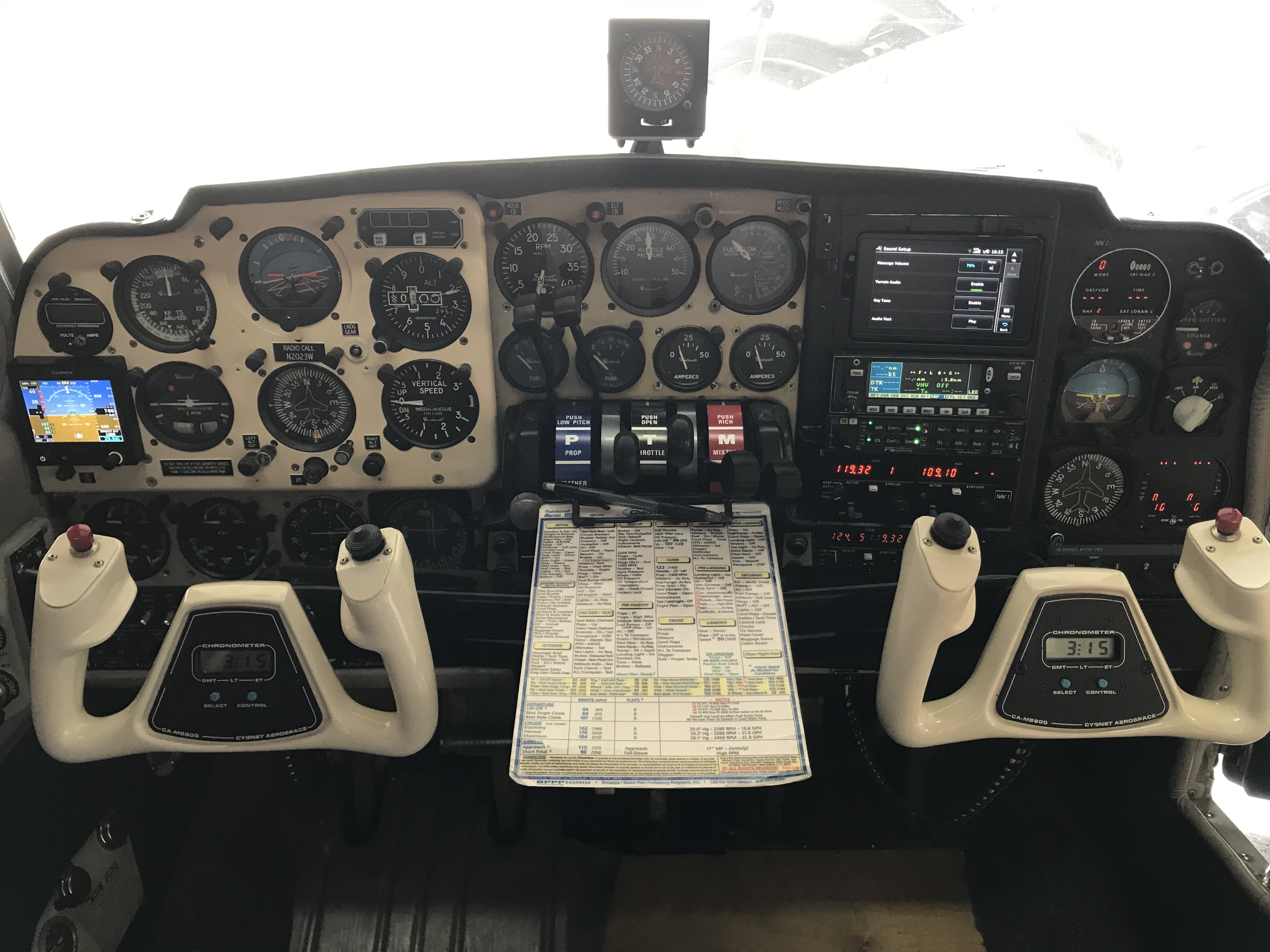
AV30
Modernizing the panel with a pair of AV30s while retaining the CIII AI & DG for AP functionality.
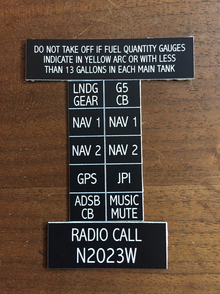
The project wouldn't be complete without fresh
placards for everything. These were made at my local trophy shop at, in my
opinion, reasonable prices.