|

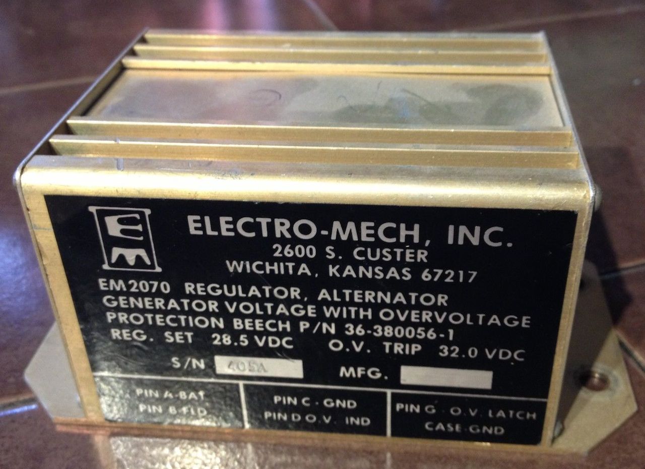
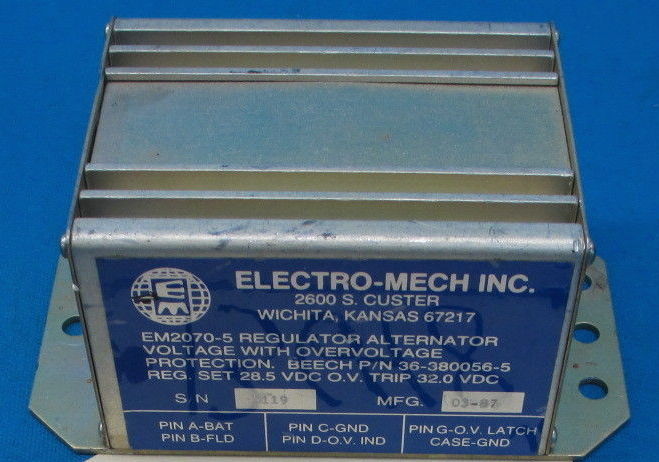
Do you have one of the above voltage
regulators that has ceased to be a regulator? If so, and you're the curious
type, you're sure to appreciate this outstanding piece of circuitry teardown and
analysis by Baron 58 owner Derek dB.
Click
HERE to get
his PDF narrative.
Here is more voltage regulator schooling from
Derek as posted on Beech Talk
HERE:
Your vintage Baron has two regulators-- one is in use and the other is a
backup. The one regulator in use simultaneously supplies the field current to
both alternators. The field current creates a magnetic field inside the
alternator which is used to generate output current. The higher the field
current, the stronger the magnetic field and the greater the output of the
alternator. The job of the voltage regulator is to adjust the field current so
the alternator output is at a constant voltage (nominally 28.25V). If more
output current is being consumed than is being generated, the voltage drops and
the regulator increases the field voltage to keep up with the demand. The same
happens in reverse-- if the alternator output current is more than is required
by the electrical system, the bus voltage increases, which causes the regulator
to decrease the field current.
The left and right alternator outputs get joined on a common bus bar under
the nose baggage compartment and this is where the voltage regulator senses the
bus voltage. This type of setup is not a true paralleling of the alternators but
is instead two separate half systems (a left and a right) tied together. The
most efficient half system will drive the bus voltage and the other half will
"be along for the ride".
If the half systems are perfectly matched, both alternators will have
identical field vs. output curves and will be outputting exactly the same
current at exactly the same voltage with exactly the same input field current
and the alternators will share the load equally. But if there is any
difference in either half system---for example, a higher resistance on one side
in the loop from the voltage regulator field, to the alternator, to the bus bar,
back to the regulator, or if one alternator is stronger than the other---then
one alternator will supply more of the load. This is the case with almost every
Baron in existence because things are rarely perfectly matched (one can spend a
lot of time getting it close). Because the currents in these loops are large
(tens of amps for the alternators and 3 or 4 amps for the field), milli-ohm
differences can result in large voltage changes.
Sometimes, as might be your case, the half system imbalance is so large that
one alternator dominates and supplies all of the required current and
effectively keeps the other alternator off, which the system senses as a failed
alternator (the alternator out light will stay off as long as there is voltage
at the aux pin of the alternator; when the alternator output is low or zero,
that aux voltage is also low or zero). When that dominant alternator can no
longer can keep up with the current demand, its voltage will start to drop,
which will cause the regulator to output more field current, which will in turn
cause the second alternator to start to output current and take up the load (the
added field current will have little effect on the previously dominant
alternator because that alternator is at, or is reaching, its limit). This could
be what is happening when you turn on your landing lights.
Since the regulator is common to both alternators (both fields are supplied
from a single regulator pin), the problem you describe with a single alternator
is not likely due to the regulator. I would start looking at every connection in
the common bus bar-->regulator-->field-->alternator-->common bus bar loop,
(ground connections, too). If everything there is clean, then the next step is
to look at your left alternator.
Here is some Bonanza VR troubleshooting advice from Derek for a fellow Beech owner's alternator woes:
John's alternator behavior sounds a little different, and I agree
with Stuart that the root cause is probably in the field segment. I
do not think glass fuses are your problem as I believe those are only
in the 'alt out' light circuit and your voltage reading shows your alt
is indeed out.
But first, it wouldn't be Friday if I didn't include some theory---
As everyone knows (or should know), electric current is produced when a
magnetic field moves past a wire and, conversely, a magnetic field is
produced when current flows through a wire. Adding more wires or
more current adds to the effect, and an efficient way of putting a bunch
of wires
in a small space is to wrap them in a coil. An alternator uses
both of these traits to produce current: first it flows a
relatively small current (the field) inside a coil to make a magnet,
then that magnet is spun inside a larger coil of wires to produce a
bigger current, which is the alternator output.
The stronger the field current in the magnetic coil, the stronger
the magnet and the higher the alternator output. The voltage
regulator is there to adjust the field current to keep a constant
voltage on the bus.
An aside-- it is sometimes said that an alternator produces AC and a
generator produces DC, but that is not exactly true as both inherently
produce AC. The generator rectifies the AC mechanically using a
commutator, whereas the alternator does so with diodes.
Oh, and another thing-- calling it a generator is technically imprecise
because an alternator is also a type of generator. What is
traditionally called a generator on vehicles is really a dynamo.
Both alternators and dynamos are generators that use a coil to create
the magnet. A third type of generator uses a permanent magnet
instead of a coil magnet; this is
called a magneto.
Something else to know is that the Beech DC generation system has a
weakness in that the voltage regulator senses the bus voltage at the end
of the very same wire that is flowing the field current. The
field current could be a couple amps, which means a very small
resistance---only a couple hundred milliohms---is all it takes to
totally screw up the voltage control loop.
So, WTF does any of this have to do with John's problem?
I think (and Stuart might be on the same page) that John has a high
resistance somewhere in the DC generation loop, quite possibly in the
field supply part of it. I further think that the intermittent
piece of it has to do with heat, i.e., at first the resistance is small
enough for the system to stay within regulation, but because that
resistance has a small voltage drop, the VR must demand more field
current to supply the load, and that higher amperage causes the resistor
to heat up, which increases the resistance, which causes more current
to be drawn, which causes more heat, which causes more resistance....
until the power loss across that resistor does not leave enough for the
field and the alternator output sags enough to turn on the 'alt out'
light. Turning off the alternator momentarily lets the resistor cool,
and the cycle restarts from the beginning.
There are lots of ways to debug the system, which include bypassing
certain circuit elements, or flat out replacing them, etc., but I think
the most quantitative way is to measure the resistance of the field loop
and eliminate the offender(s). For this you need a milliohm
meter, which is nothing more than a Kelvin bridge that anyone can cobble
together using simple components, such as this one:
http://www.aeroelectric.com/articles/LowOhmsAdapter_3.pdf
Use that to measure the resistance between the alternator output and the
field input. If it is more than, say, 300 milliohms, look for the
circuit element that has the high resistance. It could be wires,
crimps, connections, CBs, switches, etc. Check also the alt
grounds to aircraft ground (e.g., engine block) and airframe ground to
aircraft ground. Replace or fix the connections that are bad, and
don't be surprised if it is more than one (and I am not sure I agree
with Stuart that the alt switch is a breaker. If that were true,
there would be no need for a separate field breaker. And
incidentally, there *is* a way to "pull" the flush field breaker:
ground its output and turn on the master. <g>)
At least you have it easy with all the circuit elements within reach,
try measuring resistances between the left and right nacelles of a
Baron!
Good luck and try not to let the smoke out of the wires.
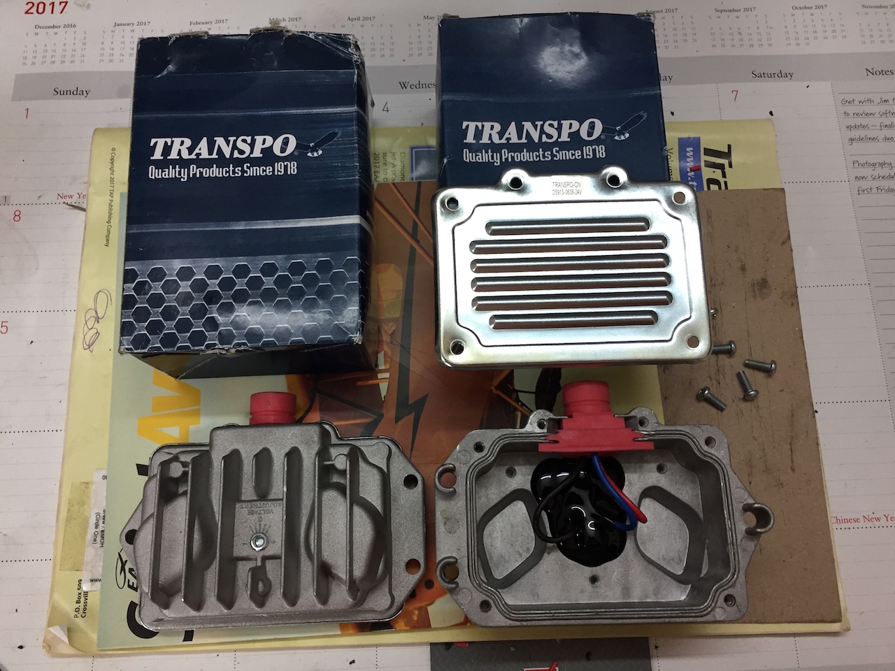
This Baron voltage regulator is typically a Delco PN: 9000591 which
consists
of very old school components that have likely not aged well. Here is a
new solid
state version that can be found, the Transpo PN: D591S and shown below.
The Transpo lists itself as a replacement for the Delco 9000591.
Amazing
that the small potted section of the Transpo is all that's required. Look for the D591S on
eBay. It holds a rock solid voltage!
Click HERE for the Transpo Catalog which shows the Delco 9000591 interchange/compatibility.
Click HERE or HERE for a reasonably priced source for the Transpo D591S.
Be sure to consult your A&P/IA for replacement suitability.
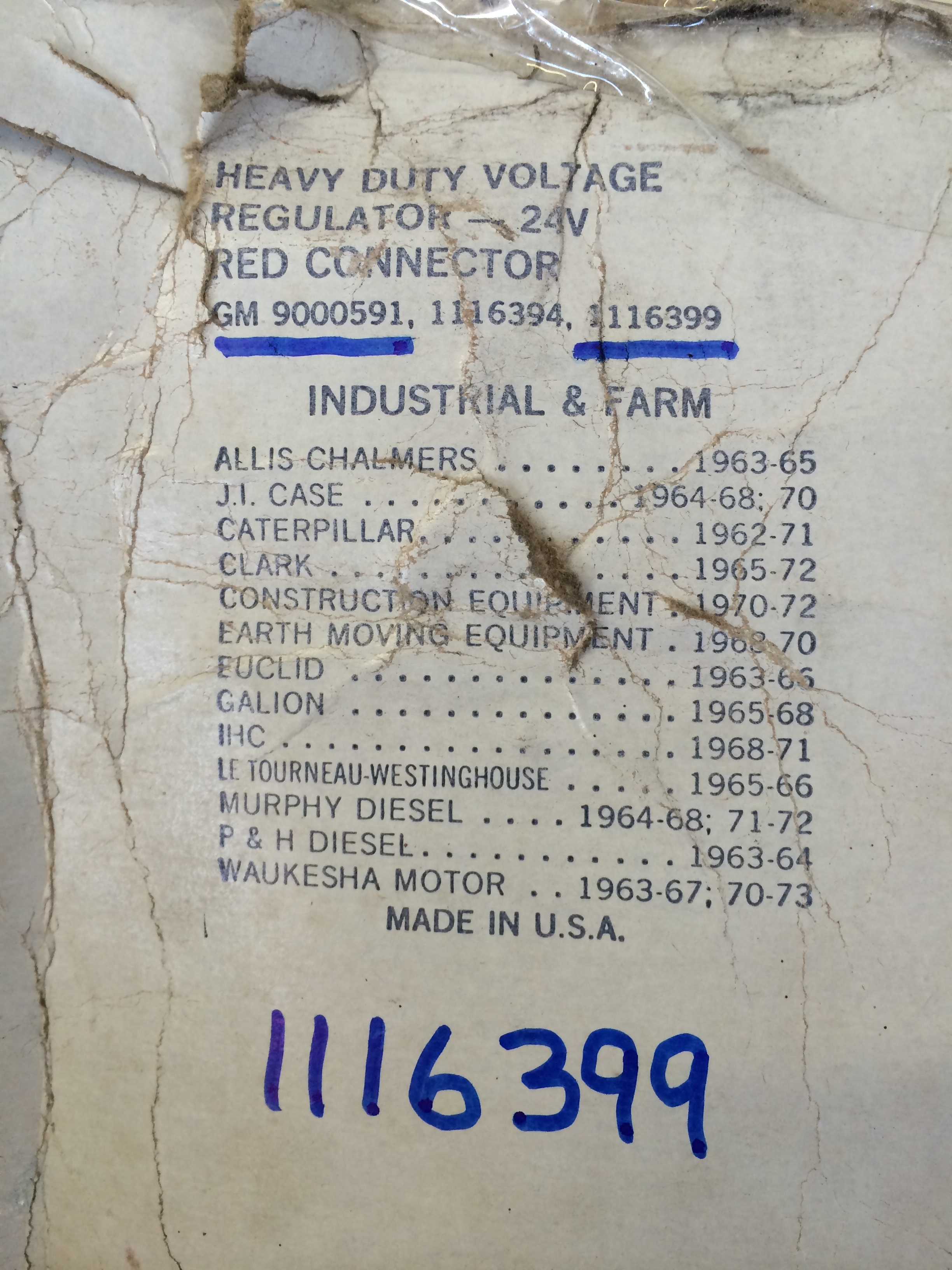
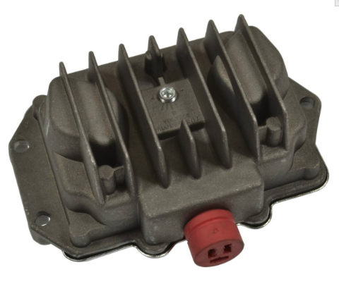
Below is an image of the early Baron Delco
9000591 voltage regulator which is supplied in pairs for the early alternator
equipped Baron 55s. Also below you will see the Farm & Industrial applications
that this same voltage regulator used to serve back in the day. Proof once again
that Beech utilized common industrial hardware of the day in many areas of the
aircraft!
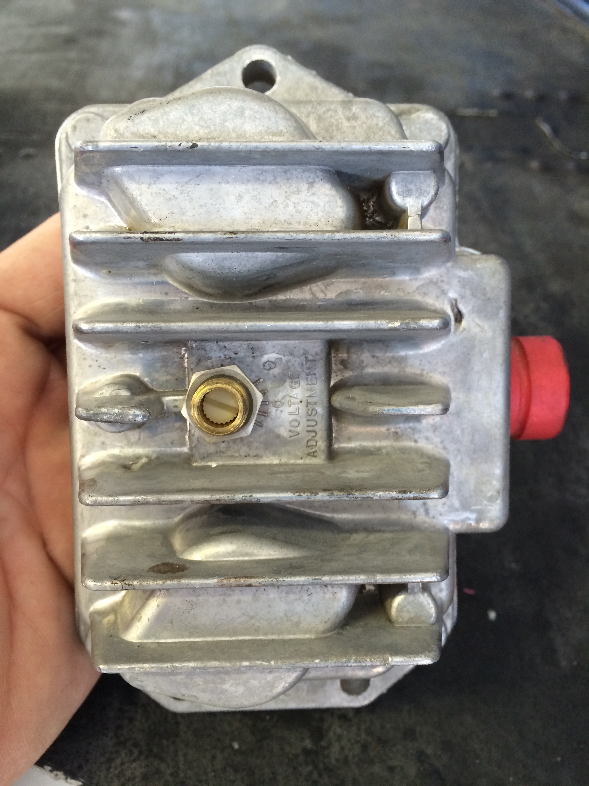
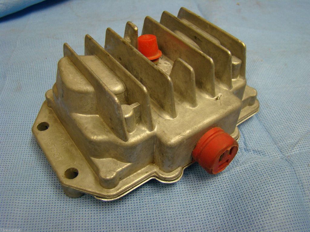
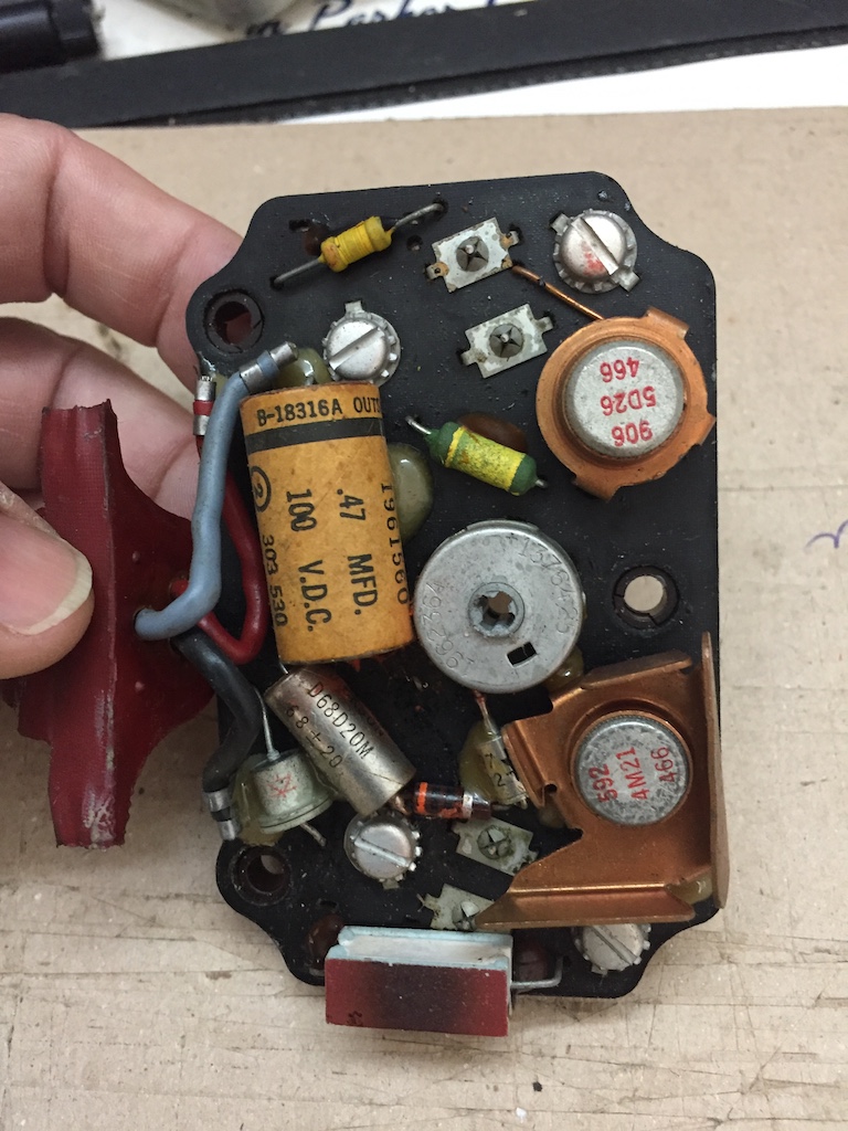
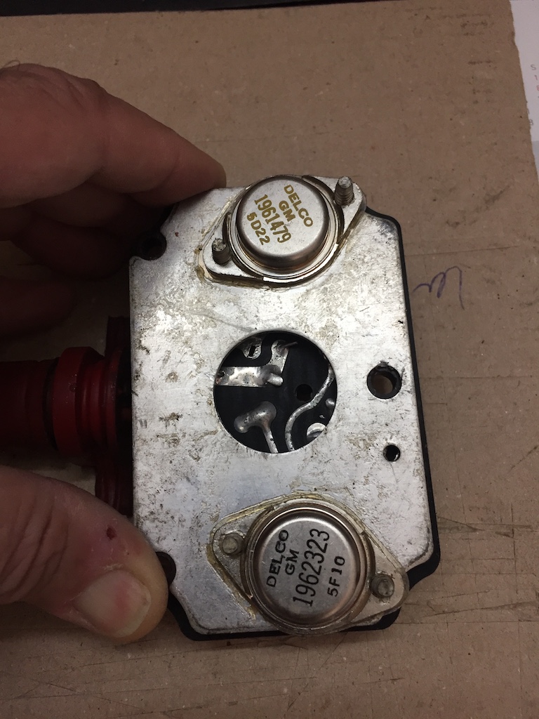
There are two power transistors within the Delco
Voltage Regulators shown above which can become tired after decades of service.
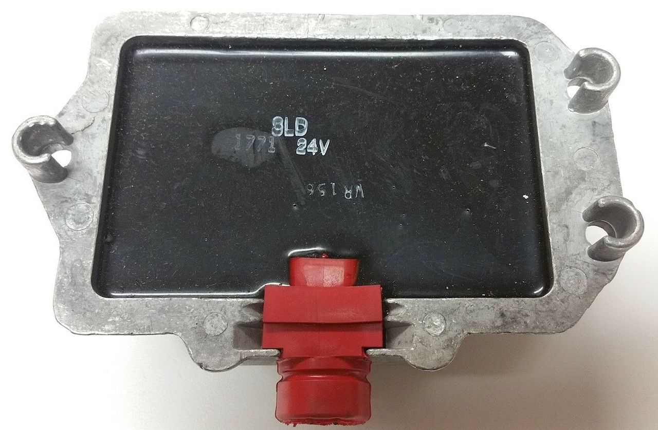
There appears to be another 24V
Regulator with a similar case and footprint in the form of Standard
Ignition's PN: VR135 which may have been supplied to agricultural
equipment. I found it available from O'Reilly Auto Parts for $58
(4/24/2024) HERE. It is pictured below.
Baron Delco
9000591 Interchange
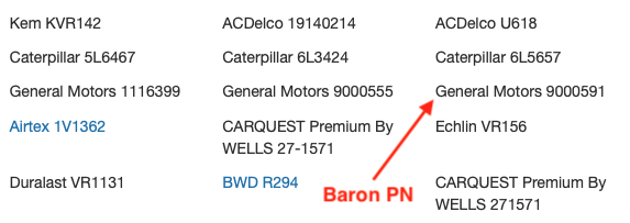 ACDelco U618 $32 @ Amazon HERE

Be sure to consult your A&P/IA for replacement suitability!
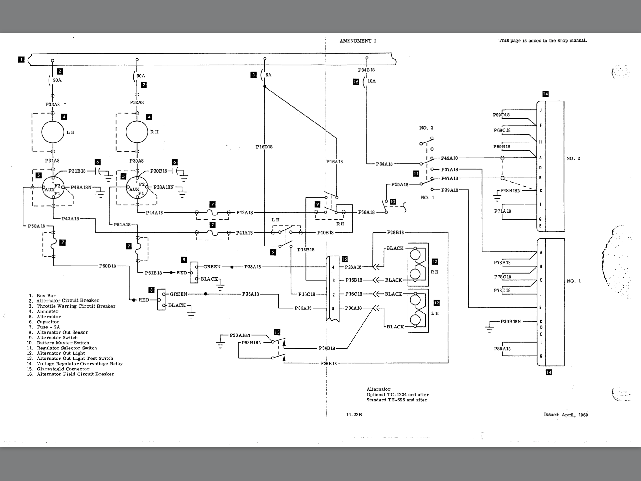
Below is an early Baron charging circuit
diagram - be sure to note the applicable SNs for it!. Check your Shop Manual for
your SN for your specific diagram:
Thanks Derek!
Early Bonanza Delco-Remy Generator Voltage Regulator
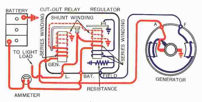
Click
HERE
for an excellent primer on the operation of the early Delco-Remy Generator
regulator.
HERE is a link to the Delco-Remy Regulator Service Bulletin from 1953.
HERE is a link to the Delco-Remy Regulator Service Bulletin from 1960.
HERE is a link to the Generator Service Bulletin from 1961
Still sick of 1950's generator and regulator technology
and brownouts in your airplane during night ops? Ready to pitch the whole
system? Consider the
Plane Power ER14-50 generator conversion kit for E-Series Bonanzas
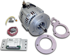
HERE is a peek
at an older install manual for the Plane Power ER14-50 conversion kit.

|