|

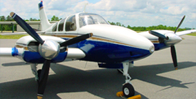
Do you have an unlimited choice in flap
positions for your Beechcraft? If your system is like mine, you have a flap
handle with UP, DOWN and center OFF detents allowing the pilot to stop the
system manually without a flap position indicator?

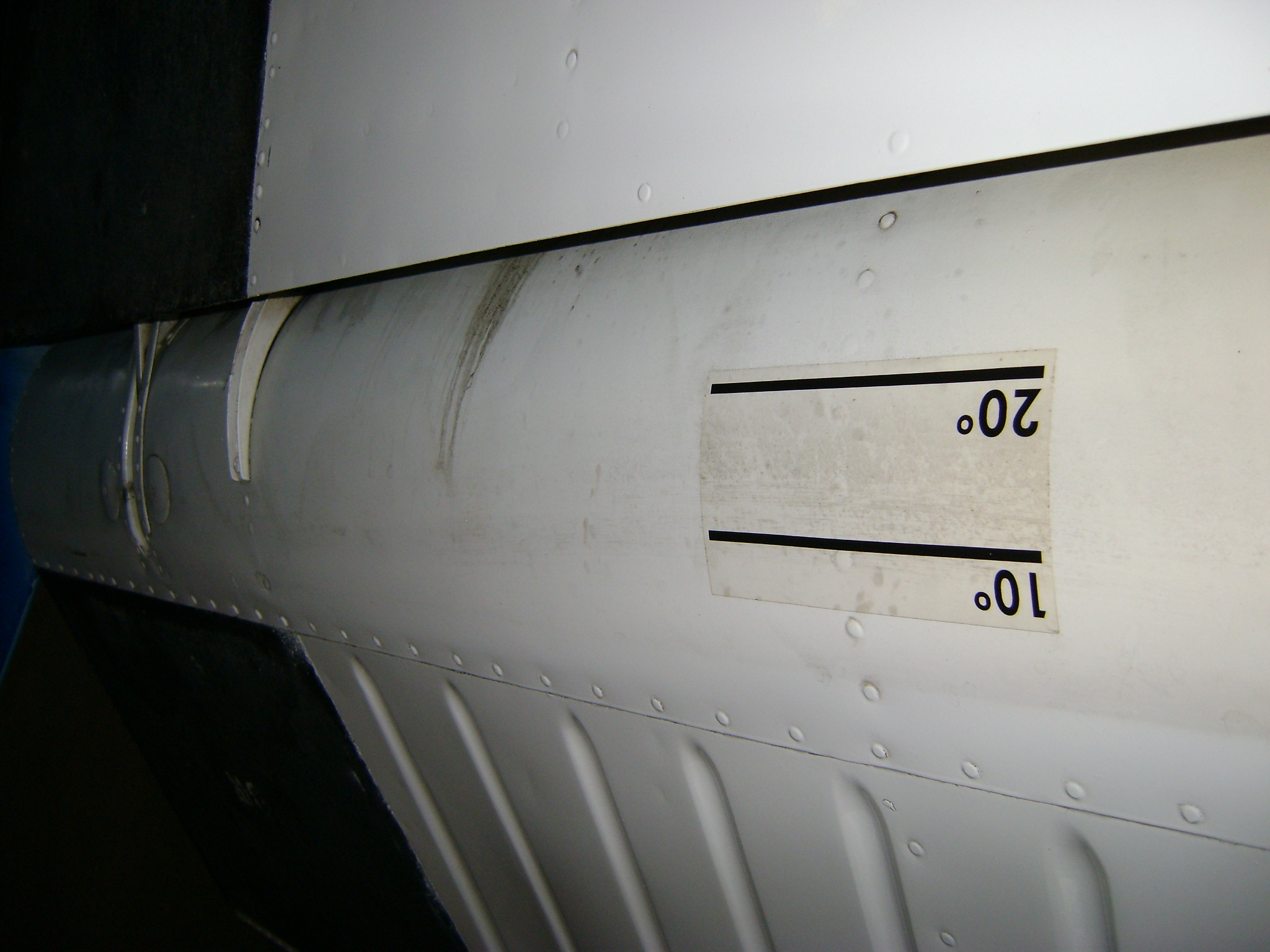
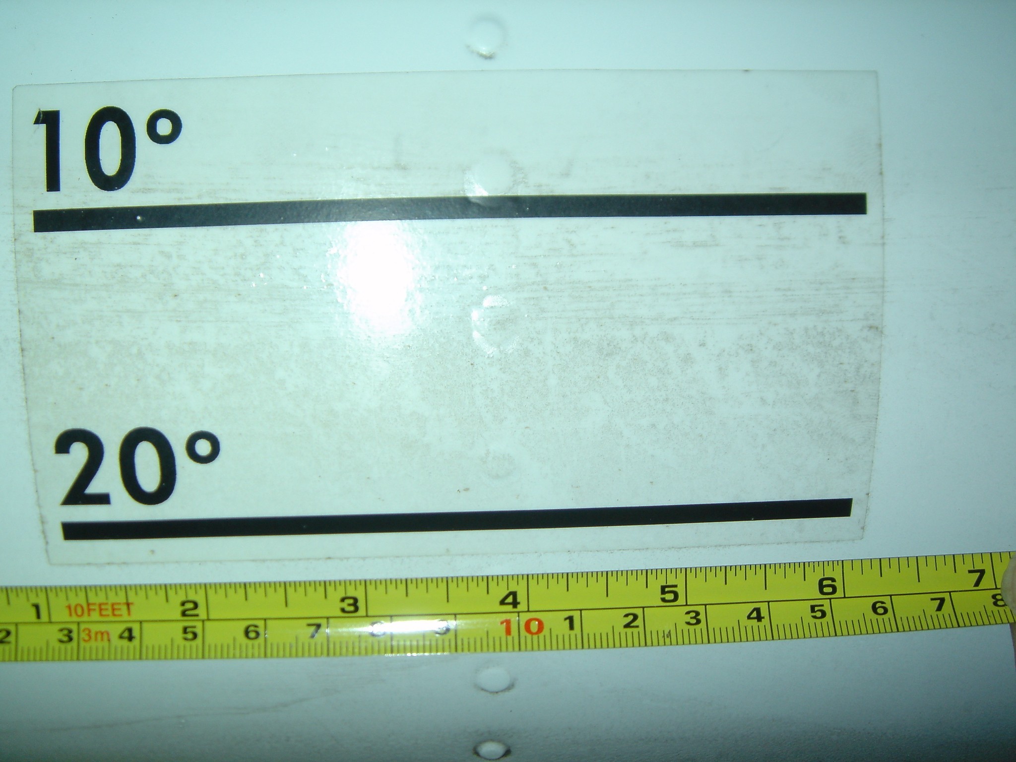
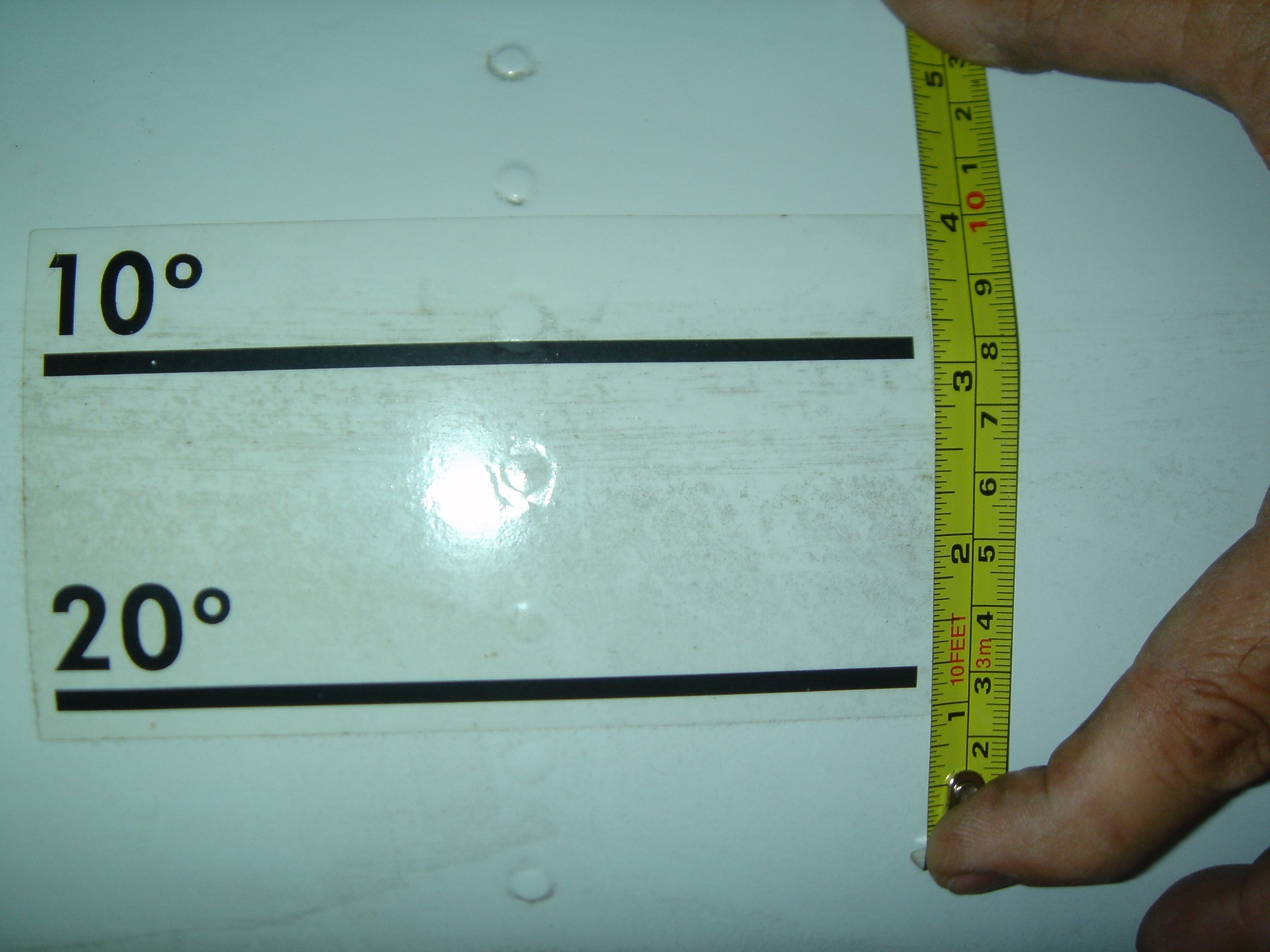
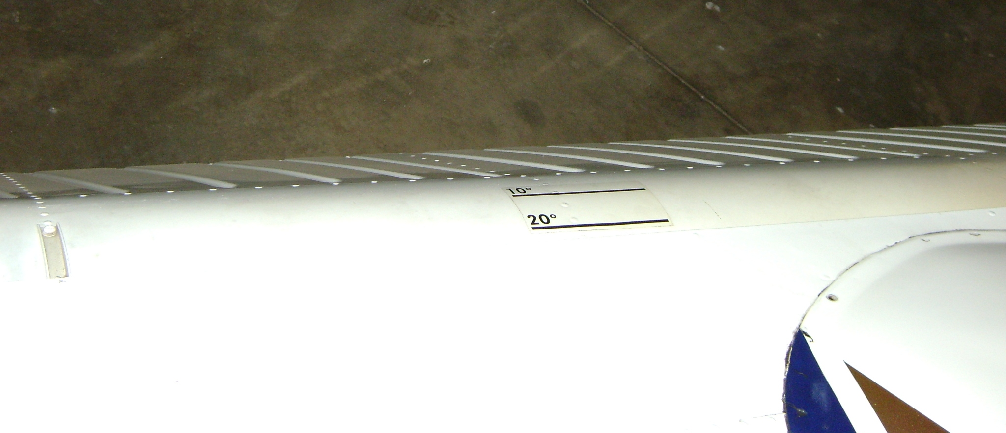
Well, here is the Beech Factory Flap decal
that can help you identify how many degrees of flaps you have engaged:
Beech P/N 35-000066B/C = Black
over Clear
Beech P/N 35-000066W/C = White
over Clear
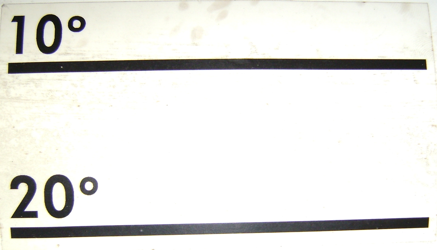
The above picture is the Black over Clear version.
Here is the way to install your flap decal on
your flap per
Old Bob, Beechcraft maven and ancient aviator:
Sit in
the pilots seat adjusted for your normal in-flight position. Look back over your
left shoulder and run the flaps down until you can see just one half of the
large (Inch and a half diameter?) washer that is on each side of the track.
When it is half exposed, you are at ten degrees.
Co-pilot Side
View
Pilot Side View
What
about twenty flap? Here is how we do that. Just roll in full right aileron.
That will put the left aileron down twenty degrees (provided of course, that the
ailerons are properly rigged). Line
up the
flap until the top surface of the flap is parallel to the top surface of the
aileron and you will have twenty degrees of flap extended.
There you have it. You're ready to spiff up
your flap(s) with a nice factory decal to tell you where you're at on flap
position. Of course, if it's pitch black dark outside you're back to the old
time count.
"Roll Your
Own" With Help From Pics
Here is
Dr. Dave Rogers
method for measuring your flap deflection:
You can easily measure the actual deflection either with one
of the inexpensive electronic angle gauges or simply by using two 1/5 x 30"
straight sticks a couple of spring clamps and a protractor.
Simply hold the sticks together, lay them on the wing about 5"
out from the fuselage and align each of the sticks with the wing and deflected
flap. Clamp the sticks together, carefully remove, draw a line along the edge of
one of the sticks onto the other and measure the inclination of the line with
the protractor or better yet a digital level/protractor.
"Be aware that because of the way the wing is built that the
actual measured deflection is different depending on where you measure. You can
see this using a digital inclinometer at various locations along the flap."
"For
the flight tests, I measure, and specified, the deflection at 5" outboard of the
fuselage mid-chord on the deflected flap compared to the inclination of the wing
trailing edge at that point."
Here's Dr. Rogers' images to demonstrate the way to use the
digital level/protractor on the flap:
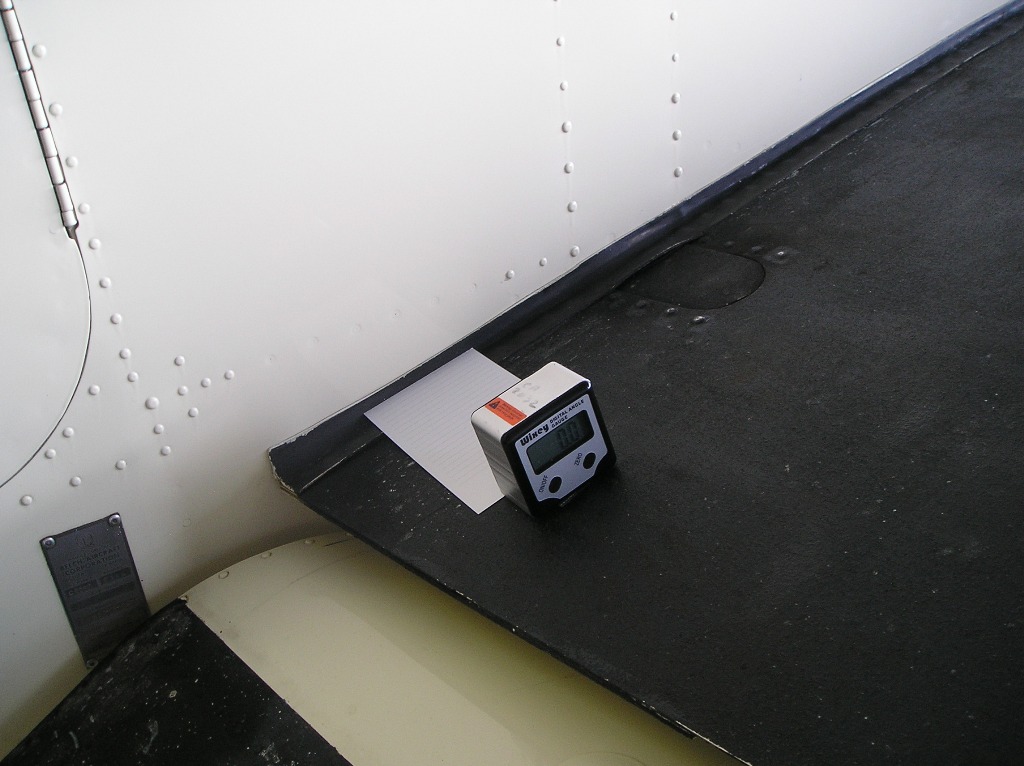
Top of wing - Set Zero
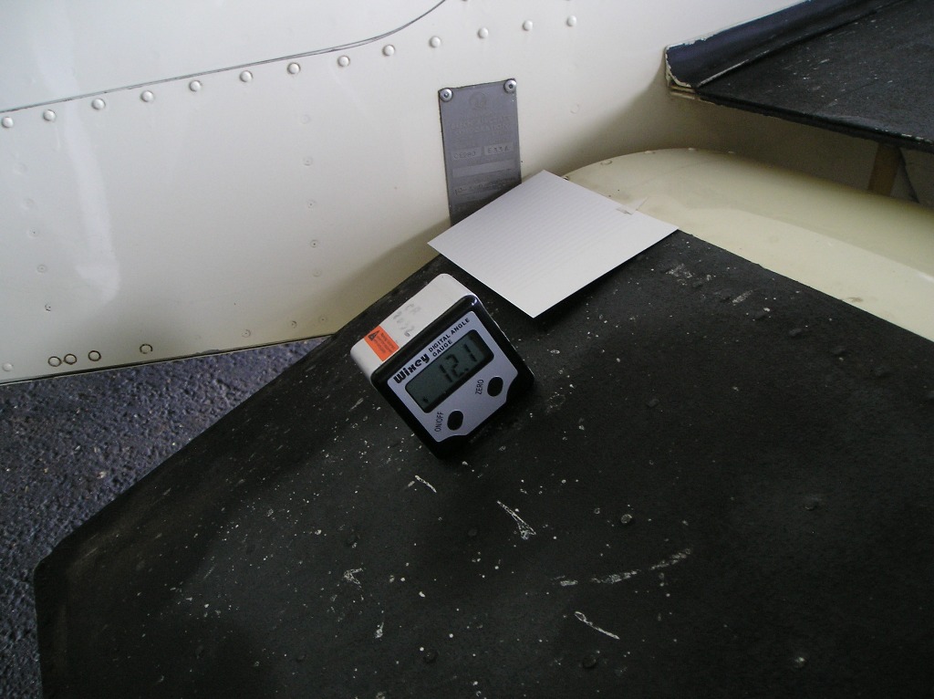
On Flap - Take Reading and make appropriate
markings on flap and/or indicator.
Now when you want 10 degrees of approach flap
or 15 degrees of flap for a short field takeoff, you'll have a good way of
knowing (at least in daylight) where your flaps are positioned.
Here's my view from my office
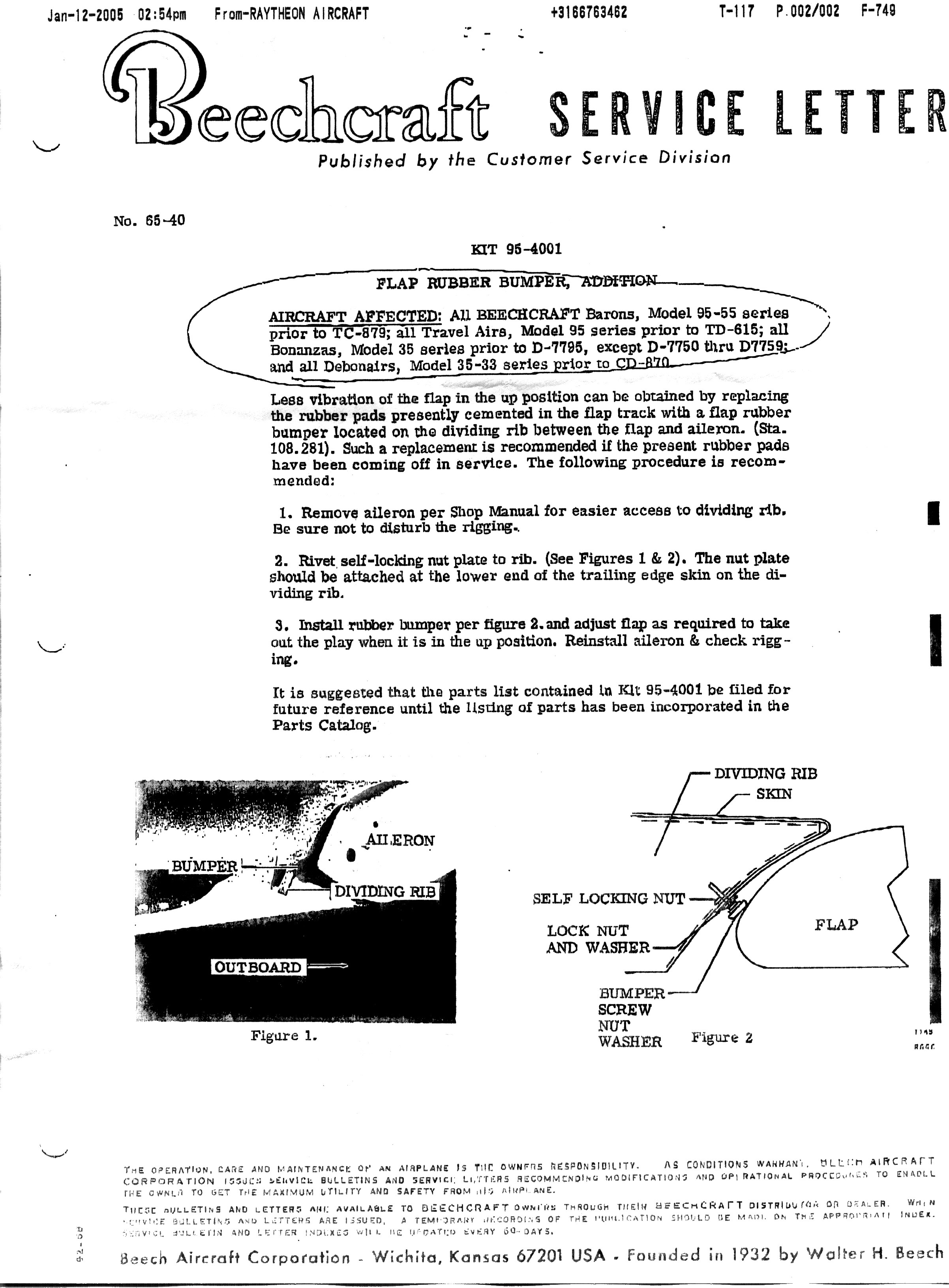
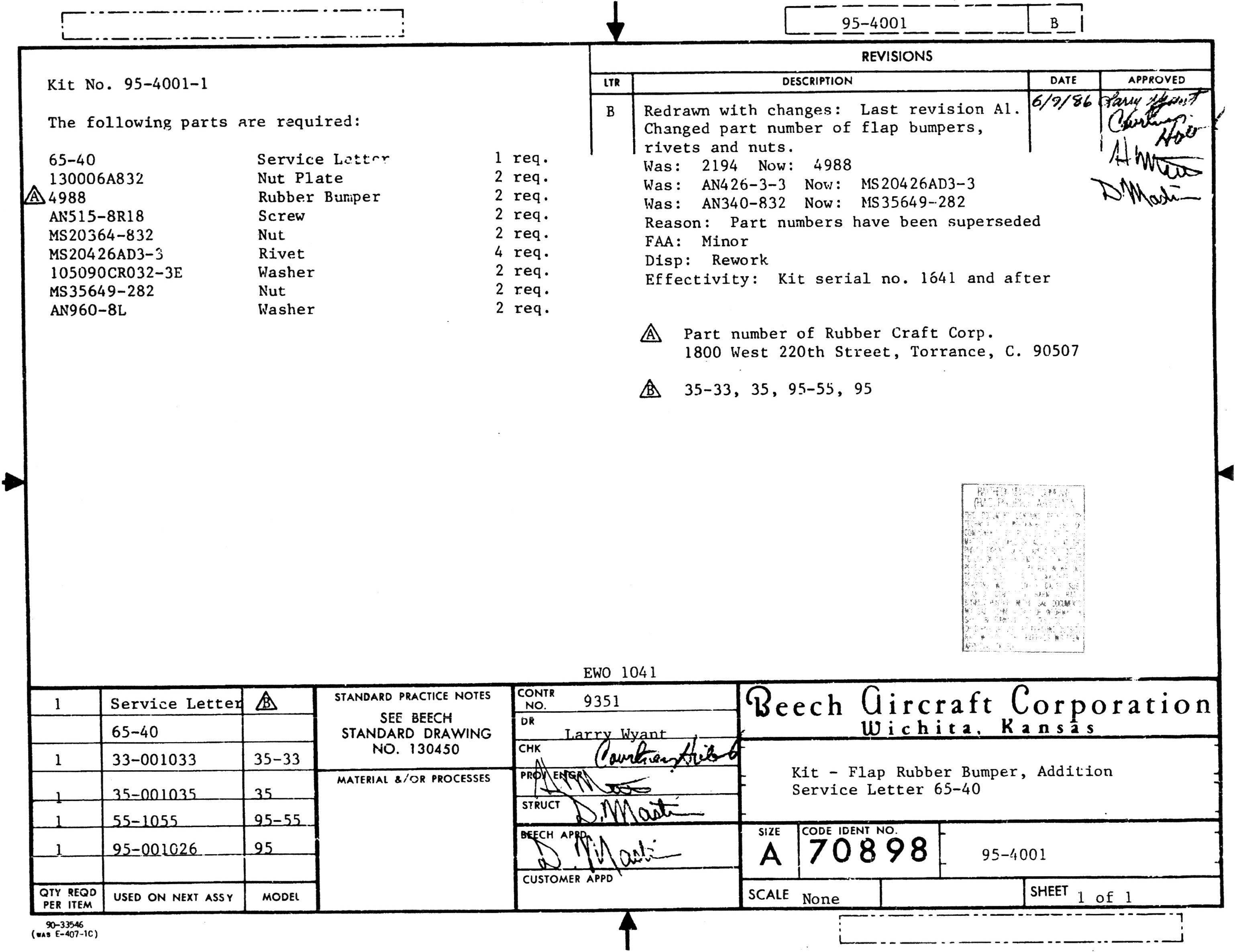
Flap Bumper Repair Kit
Does your flap rattle or vibrate
in flight in the full up position?
Beech Kit #95-4001-1 is designed
to give you the little pieces and a rubber bumper to be placed in the airframe
for the flap to come to rest on.
Thanks to Beech Lister Jim H.,
here are the pics of the
parts list for Kit #95-4001-1 and the Beech Service Letter 65-40 that describes the
installation of the kit. Here are his pics on his F35 Bo. Here are Jim's
comments:
"The kit is installed on the outboard end of each flap.
Picture 1 is taken from beneath the flat look up and outboard. Picture 2 was
taken from above the flap looking forward and slightly outboard. The end of the
left aileron can be seen in both pictures. The kit was installed per Beech's
instructions with little or no problems. The biggest hassle was removing the
aileron, that's a must, flap doesn't have to be removed. Flaps are now nice and
snug when retracted."
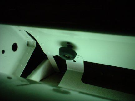
Pic
#1*
Pic #2*
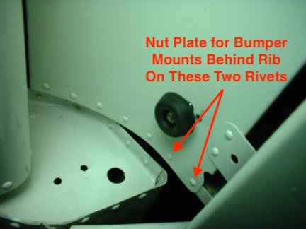
*SPECIAL NOTE
regarding the pics above: I am told by an experienced IA that the pic above
displays an INCORRECT flap bumper installation. The bumper should be installed
on the rib, NOT the sheet metal where it is shown attached. The attachment
position depicted above can result in damage to the leading edge of the flap as
well as the sheet metal where the bumper is attached.
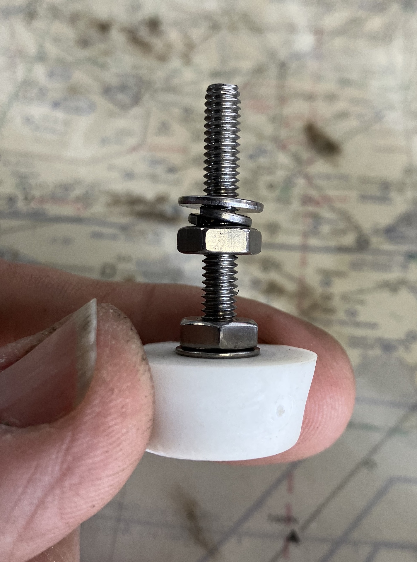
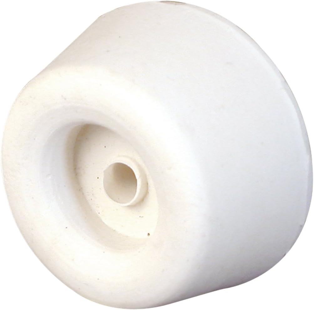
Below is a DIY Bumper Solution*
The screw is an 8-32 x
1.25"L which threads into the original rivnut, if it has not been
corroded beyond use. If you have to replace the rivnut, it's a tedious
"building a ship in a bottle" experience  . Don't ask me how I know! . Don't ask me how I know!
The Bumper* can be found HERE
You will use safety wire
pushed through the two rivet holes that you have drilled out. Then you
wrap the safety wire ends around the rivnut holes to gently pull it into
position on the back of the rib. Then you delicately thread the 8-32
screw into the rivnut to pull it into place. Then pull your safety wire
off the rivnut. Now use an awl to align the rivnut holes with the rivet
holes. Then pull your first and then second rivet. Congratulations! You
are done. (If this roadmap has helped you with this hair pulling
project, please consider a donation to the site.)
Please
Donate to Keep CSOBeech.com Free*
*On average, CSOBeech serves up over 650 pages of content each day and only a minuscule portion of our visitors
donate. If each visitor gave only $1 a month, we could keep
CSOBeech thriving for years to come. The price of a few cups of
coffee per year would be greatly appreciated. It’s your
generosity that keeps me motivated to keep CSOBeech content
current and confirms to me that the investment of my time in the
site matters to you. Your donation will insure that CSOBeech is
here for you when you need it. I hope you’ll think about how
valuable it is to have unlimited access to the information in
CSOBeech.com. In honor of our 17-Year Anniversary, please
consider a $10 donation for your annual access. Thank you. CSOB1
*with A&P approval
Click the pics below for a full
size image of the Service Letter:
Click
HERE
for more flap system info.
|