|

Alternator Out Lights: If you don't have an alternator out light OR a voltmeter,
I don't think you'll have a good handle on your electrical system, but that's
just my humble opinion. Those old ammeters can be pretty squirrelly to see a
discharge and they're usually not easy to see at the moment an alternator
failure occurs. The B55 I have and many other B55 owners report that the
alternators hardly ever parallel and share load so that you can see some load
being taken by both alternators indicated on the ammeters.
Lots of Baron owners end up looking at one ammeter showing a load and the other
at zero. One would never know if the alternator showing zero load had failed,
until it was too late! This issue has troubled me for several years and I
finally solved it with alternator out lights that were optionally configured in
later Baron models. Here are ways that this can be accomplished,
with your A&P's
blessing of course.
Below is a picture of my Alternator Out Lights using aviation PTT lights,
MS25041.
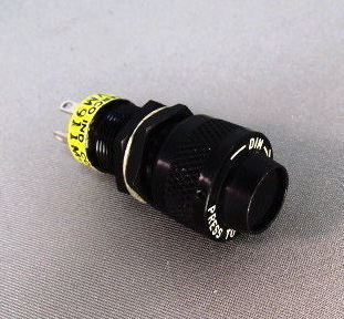
My
green lights have since been changed to blue lenses that I was able to source at
ASOD.

Most older Barons and maybe
Bonanzas with belt driven alternators use the Delco or Prestolite design. First,
take a look at the Alternator Wiring Diagram PDF extract
HERE
to see the various factory alternator out configurations.
You will see references to Alternator Out lights and annunciators using a relay
and also a "sensor". I think the sensor is just a microelectronic
relay, but don't take my word for it.
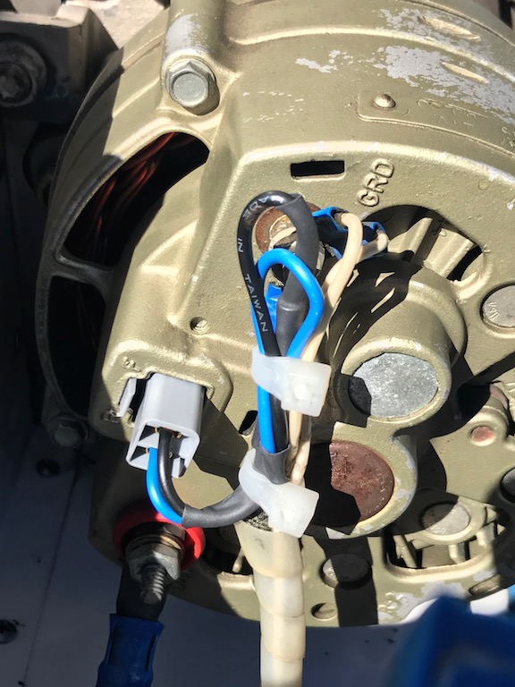
With this info you can see exactly how the
factory used the "AUX" terminal of the Prestolite alternator or the
"R" blade connector on the Delco alternator. These terminals provide
one-half the voltage rating of the alternator when the alternator is making
juice. So, on a 24V system, this will be in the 12.5V - 14.5V range. This is key, because it will
allow you to use a conventional CSOB 12V DC relay available at Mouser,
OnlineComponents,
Allied Ellectronics or NAPA with or without a socket base, to configure your alternator out
light.
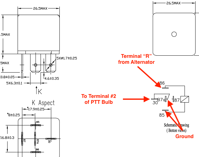
Here is how one might wire a conventional 12V
DC Relay for Alternator Out light functionality with a MS25041 PTT Fixture:
These are the Delco Alternator PNs from the
B55
TCDS: 50 Amp Delco-Remy 1100685,
1100718
and 1100747.
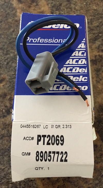
Here is an excellent AC Delco connector found
by Bonanza TC owner Brandon E. for his Delco alternator, PN:
PT2069 for consideration that can be found on
eBay or
Amazon which will make your Delco Alternator Field and "R" connections much
more robust.
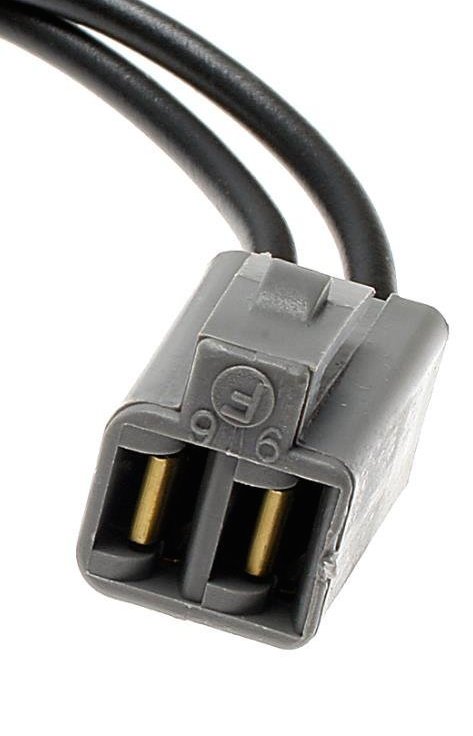
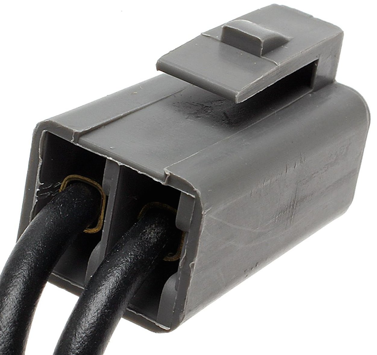
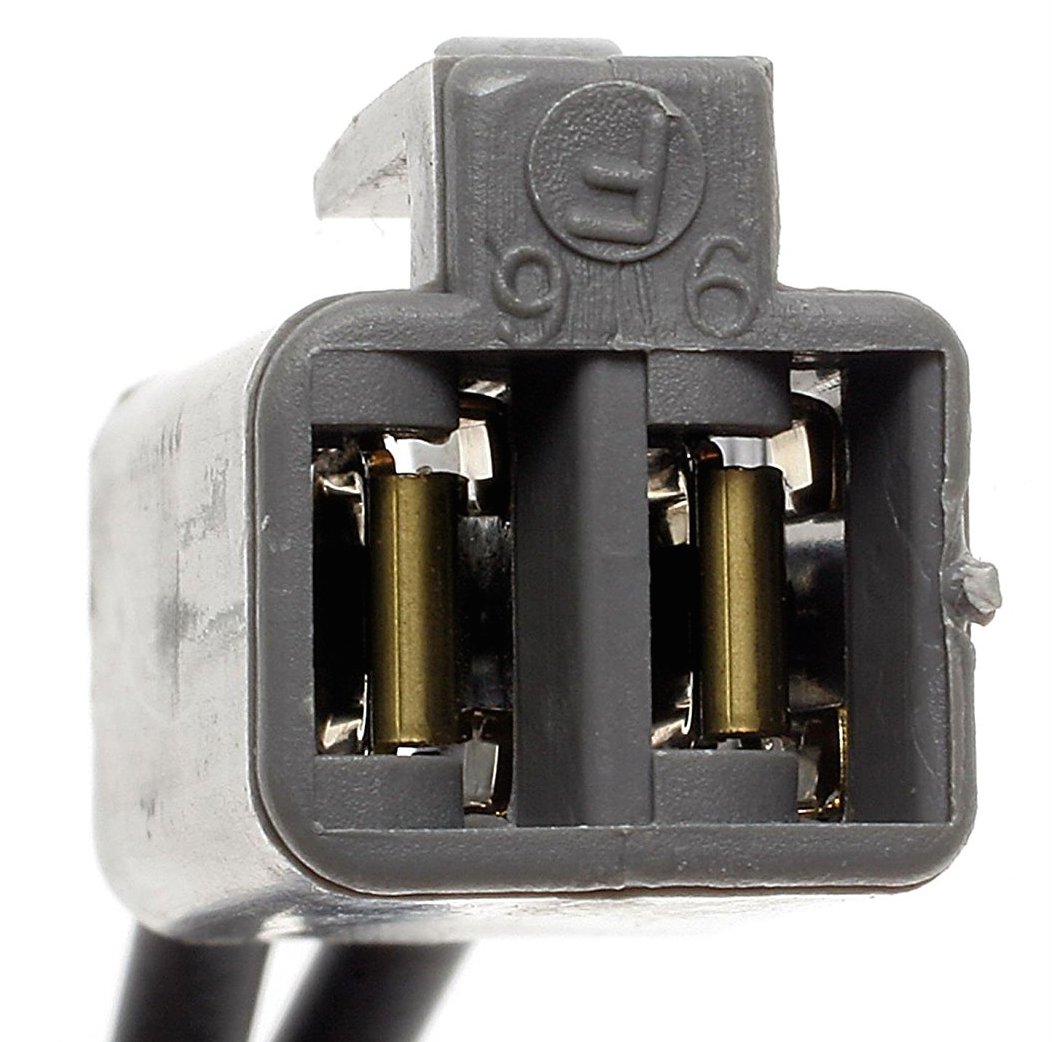
Here is what the PT2069 connector looks like
in the Delco case, a very nicely insulated connector for those two terminals, in
my humble opinion

Here is an approach
taken by a Beech Lister for his alternator Out light install:
He used the Lamar
relay PN: A-00258-2, $77 ea from
www.airsuppliers.com
since it is called out on the B55 wiring diagram/parts catalog. This relay is also
used by Piper under PN: 587 857. He also used the Sloan lights as they are
reportedly the supplied lights for current Beech models PN:
102-SI
lights & 102-STD-RTP red lens, a few bucks from
www.Alliedelec.com
See the Sloan Light Bulb Data Sheet HERE
or use conventional
PTT
MS25041 (Push To Test) aviation fixtures.
Another approach to the
project for review with your A&P with Delco alternators might be:
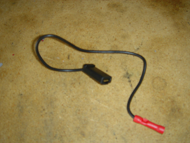
Go to National Aviation Parts
of America (NAPA <grin>) and buy a single female plastic covered blade
connector with a little length of wire attached, see pic
HERE
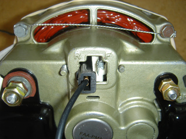
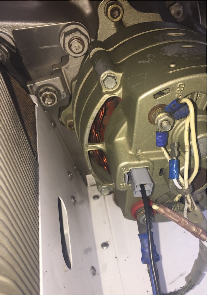
(or, better yet, get the PT2069 connector
above). This will go on the "R" terminal of the Delco regulator, see pic
HERE,
(use a regular ring terminal if you are connecting to the Prestolite AUX
terminal) and is nice because the plastic housing around the female connector
insulates the connection from alternator case grounding (a bad thing) and the
"F" field terminal which is right next to the "R" terminal.
Use of PT2069 connector will give good insulation between the terminals and the
case body.
Find a glass fuse holder and
insert a 2 amp glass fuse in it. Connect this fuse very close to the
"R" terminal connector that is connected to the "R" terminal
of the alternator.
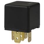
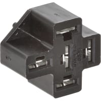
Now get the best 12V relay you
can find (see above suggested components) and a connector base that plugs into the relay with short lengths of
wire for relay connections or use the Lamar Relay
PN: A-00258-2
or the same thing under a Piper PN: 587 857.
Connect the fused end of the
"R" terminal bladed connector you put on the alternator to one side of
the relay actuating coil. Ground the other side of the relay coil to the
grounding lug on the alternator.
Connect
ONE side of the NORMALLY CLOSED contacts of the relay to the alternator
ground lug.
The OTHER SIDE of the NORMALLY
CLOSED contacts of the relay will be carried up through the wing to the #2
Terminal of your
PTT (Push
To Test) bulb or whatever annunciator light you are using. This is carrying GROUND up to your
PTT
bulb
through the wing so no dangerous voltages can short out in the long
wire run in the wing.
The PTT bulb is wired to
+24volts from the master bus on the #1 center terminal. The #3 terminal of the
PTT bulb goes to ground (so you can test it). The #2 terminal of the PTT bulb,
goes to the wire you just pulled through the wing. You'll need two 24V lights of
some sort. Red, blue or amber lenses work well and you can find them at the
salvage places listed
HERE.
Use some very nice
placard from www.engravers.net
"L Alt Out" and "R Alt Out" and you have a professional
install that any A&P would be proud to sign off.
Here is what happens in the
wiring circuit:
Alternator not running or
running and NOT making juice = no 12-14V juice at "R" terminal. So:
Normally closed contacts carry ground up to PTT bulb and bulb lights up. Things
are BAD!
Alternator running making
power = 12-14V juice at "R" terminal. So: Normally closed contacts
OPEN UP and remove the GROUND from your bulb. All is good!
A location suggestion for mounting the
relays in a Baron is the backside of the cowl door baffle (through one of the rivets with a nyloc nut and screw) that is right next to the airbox. This makes all your wires
very short and a compact and tidy install. You can loosely wire tie the fuse and
wire bundle to the scat tubing going to the alternator without crushing the scat
tubing.
Hi resolution panel picture of my Alternator
Out Lights installed (green lenses have since been changed to blue, when I find
red ones I'll use those)
HERE.
A great article in the October 2008 ABS Magazine, written by
John Collins on page 10998 and 10999, discusses the history
of the alternator out lights and the components and how they work in the system.
Some very interesting Beechcraft parts,
available at
RAPID,
outlined in this article that could be of interest to you and your mechanic in
retrofitting your system with
alternator out lights are:
P/N 36-380000-1 (14V Alternator Out Sensor)
$196
P/N 36-380000-3 (28V Alternator Out Sensor)
$122
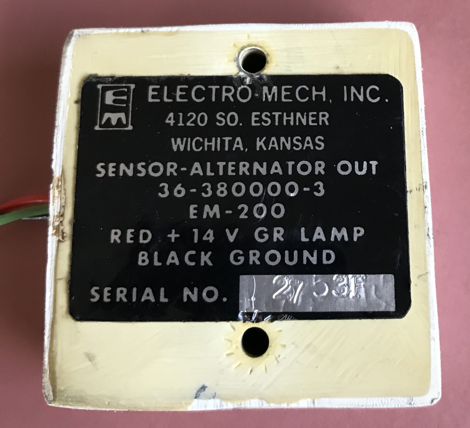
P/N 36-380000-11 (Baron Replacement Alternator
Out) $119
P/N 55-3025-1 S (Replacement PCB Kit) $108
|