(1) We put the plane up on jacks and a tail stand and
confirmed it secure.
(2) Even with master power off, we pulled the breaker
for the gear motor and relay
(3) We cranked open the inner gear doors with a few
clockwise turns (looking forward) of the manual crank and removed the inner gear
door bolts at the hinges and then placed hoses over the exposed rod ends so as
to protrude from the side of the fuselage. This insures that the rod end will go
in and out of the airframe without crashing into something immobile and bending
the rod or worse when we eventually test the system.
(4) We removed the main gear rod cotter pins and nuts
under the spider arm. We did use some movement of the manual crank to better
position the cotter pin for extraction. We applied the same philosophy to
removing the cotter pins and nuts on the inner gear door arm/uplock cable, just
a little manual cranking to get a good working position.
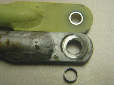
We were careful to note that there is a tiny bushing in the top of the inner
gear door arm that must be preserved for reassembly.
(5) We then removed the 4 bolts that connect to the base
of the flap motor and slid the metal plate outward toward the cockpit door.
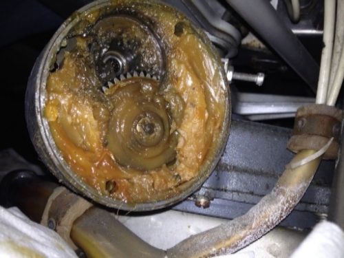
(6) With the top arms out of the way we then had clear
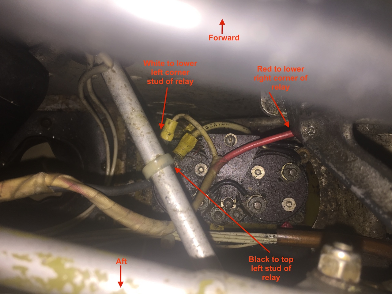
access to remove the gear motor and the dynamic brake. We were sure to
photograph the wires from the motor and their positions on the dynamic brake.
Also the wires on the aft side of the dynamic brake were marked and photographed
to insure perfect reassembly. While the dynamic brake might not have been needed
to be removed for the tranny extraction, we chose to remove it to replace it
with a very low time unit and also most importantly to renew and refresh the
critical frame grounding that the dynamic brake relies upon to do the best job
of bringing that high torque 24V/7600RPM motor to an instant dead stop when the
up and down limit switches are tripped. While still in the top end of things we
removed the four screws that hold the micro switch mounting cradle to the
airframe. Moving this cradle to the side allowed more room to wrestle the tranny
out. If I didn't already have fairly new
MS25026-1
(aka BZ-R31) micro switches, now would be a great time to replace the 50
year old switches. Scroll down
HERE to
find info on the BZ-R31 switch sources.
(7) We then went under the belly to remove the nose gear
drive arm. This required us to manually crank a little of the mechanism to
position the arm in the opening such that the rod end bolt can drop free and the
arm can be pulled off the tranny shaft down through the opening. The snap ring
was removed and the arm was able to slide free and down. A helper comes in handy
to take some pressure off the nose gear to remove the tension on the rod end
bolt. At this point we then removed the four 7/16" nuts that hold the tranny to
the airframe. Some reports of corrosion of the transmission base and the
magnesium reinforcing plate in the bottom of the mounting cavity have caused
some people to have to use jacking pressure to break this loose. Thankfully, I
did not experience this corrosion issue during my extraction.
(8) Since we had all the cranking for optimum
positioning done we now removed the three screws holding the crank handle onto
the tranny housing.
(9) Now we began our lift and wiggling of the tranny
toward the cockpit door. The removal of the wood floor section immediately under
the crank handle was essential to us in getting the last few mm needed for the
tranny to clear the bottom of the seat support frame. My years of practicing
with Chinese puzzle rings have finally paid off!
Based on my experiences summarized here, I'll offer some of my non-mechanic "opinions/observations".
My 24V gearbox had slammed into the stop back in oh, 2006. Slammed so hard
into the stop it blew the circuit breaker (and was unable to unwind it with the
crank). By the grace of God, multiple breaker resets actuating in the down
position freed up the mechanism. Loose transmission mounting nuts were the cause
of this anomaly and possibly complete dynamic braking failure (the motor
internals were toasted after this event). After troubleshooting and parts
replacement and rejigging, the gear box continued to function normally for the
next 11 years.
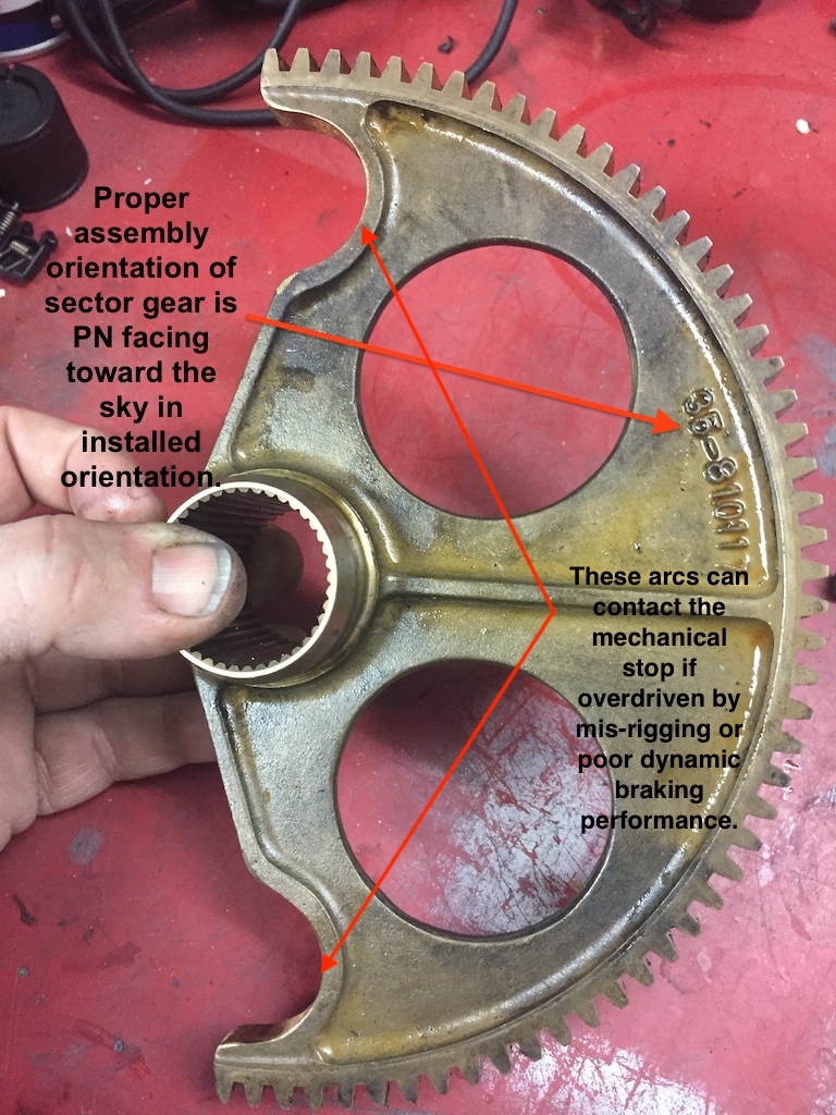
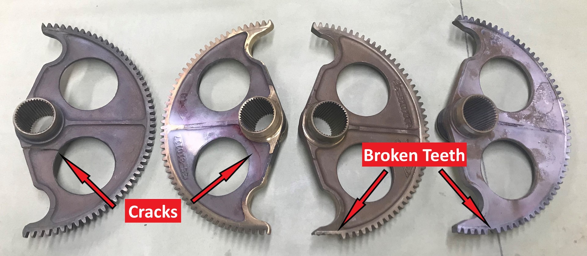
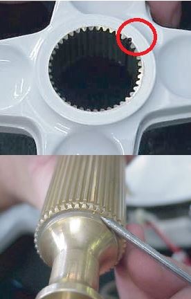
When I finally pulled my original gearbox as outlined in the above narrative,
the sector gear was in fine shape. So, in my case, strictly applying the rule of
overhauling the box when it slams into the stop would have been completely
unnecessary.
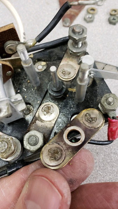
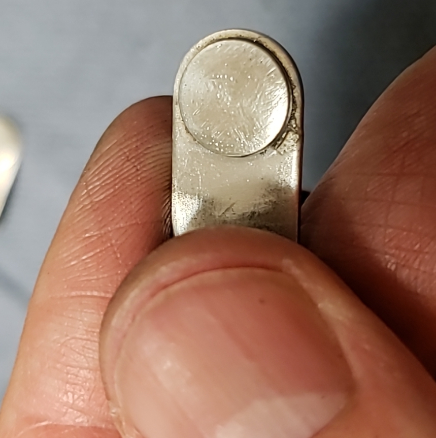
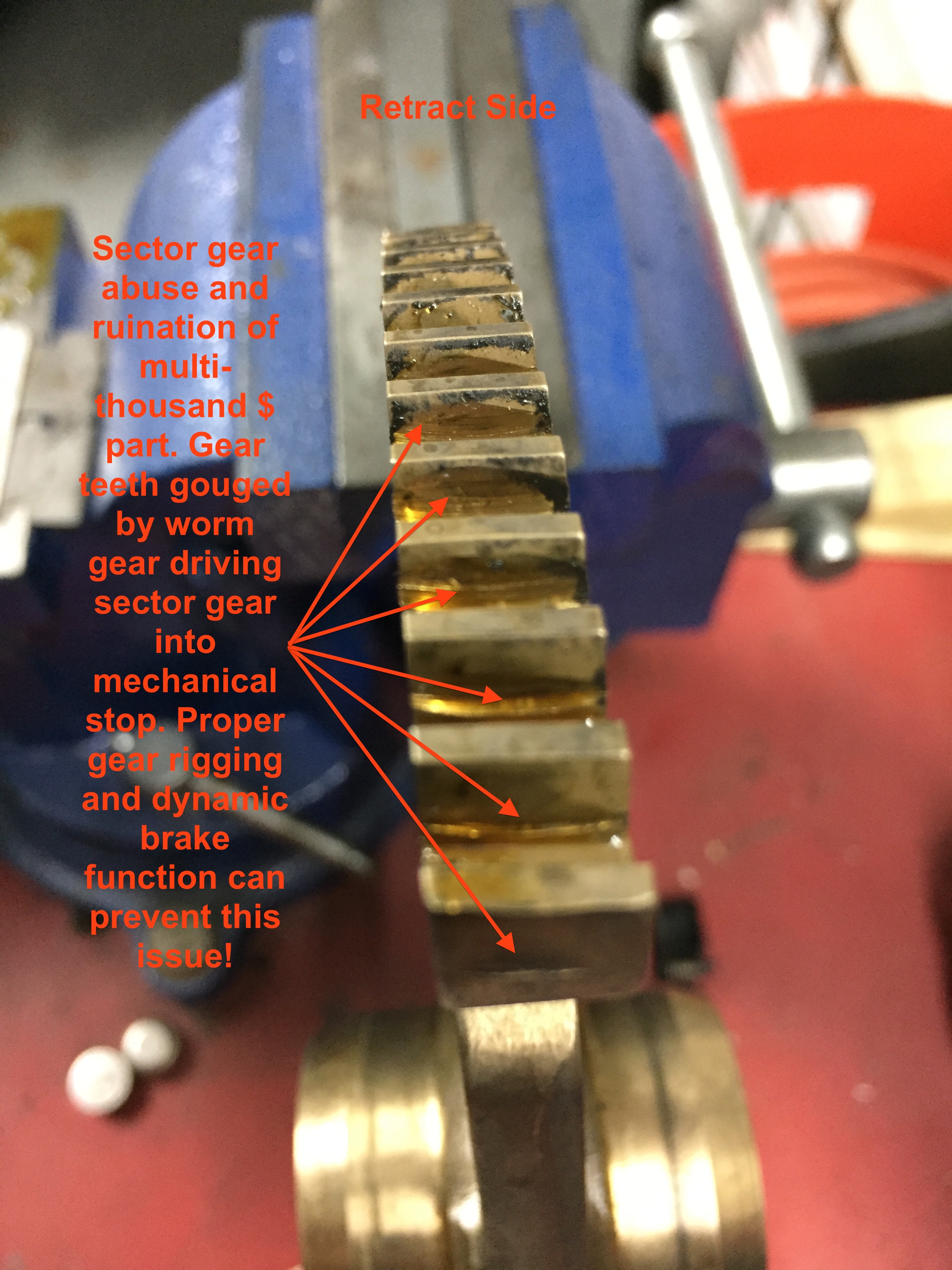
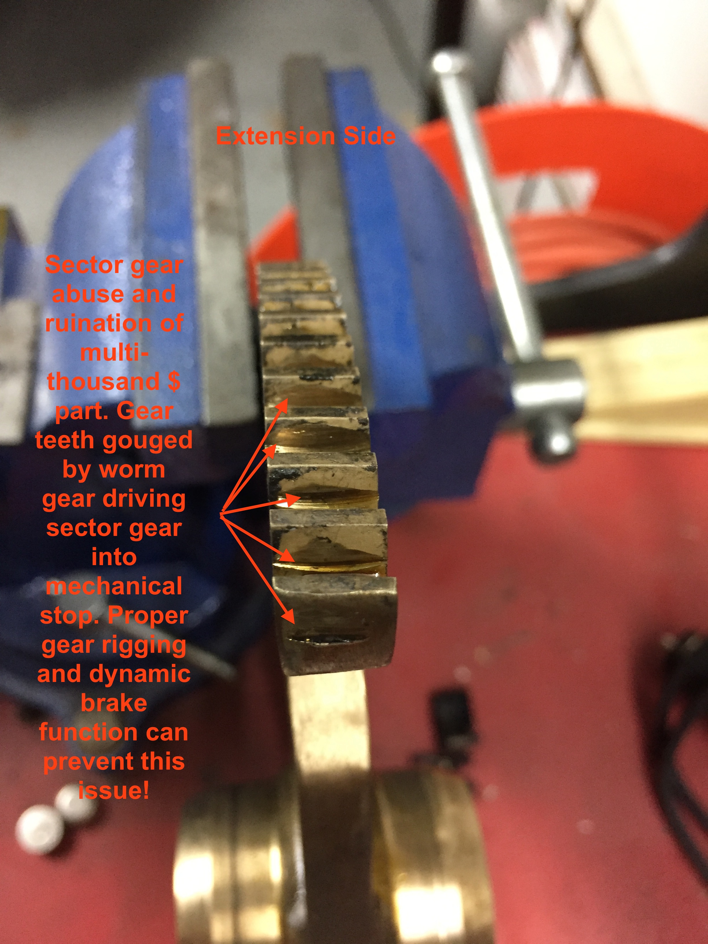
With a low time gearbox that I had on hand, I noticed that this low time box
had a significant change in hand crank resistance at the beginning and end of
crank travel. Sure enough, when I opened this gear box up to inspect the sector
gear, it was badly gouged. So, from this empirical physical observation, I could
offer that if one can detect rough or increased hand cranking forces at either
end of sector gear travel, you likely have something of a gouged sector gear on
your hands and THEN, in my humble opinion (shared by my IA), you would be
advised to pull the box and have it completely inspected and begin your search
for a viable sector gear (>$2,000 new).
So, if I were concerned about my sector gear being pranged by slamming into
the stop over a long period of time, instead of a complete pull of my box, I
would simply disconnect the inner gear doors from their rods and the main gear
rods and nose gear rod from the transmission, then freely crank the transmission
with the manual crank and feel for any cranking resistance change at the ends of
travel. You might also consider removing the gear motor itself, as it adds some
resistance to the manual cranking but you would surely notice the increased
force required by a pranged sector gear. I was certainly able to feel some ting
wrong when I was cranking the box with the badly gouged sector gear ends.
Some other thoughts to consider, taken from Kevin O.:
12V gear motors, by virtue of their speed and lower torque present a lower
risk to their sector gears.
Conversely, 24V motors by virtue of their speed and torque present a HIGH
risk to their sector gears in terms of gouging them when out of proper rig or
dynamic braking failure.
Just my $0.02 and worth what you paid for it!
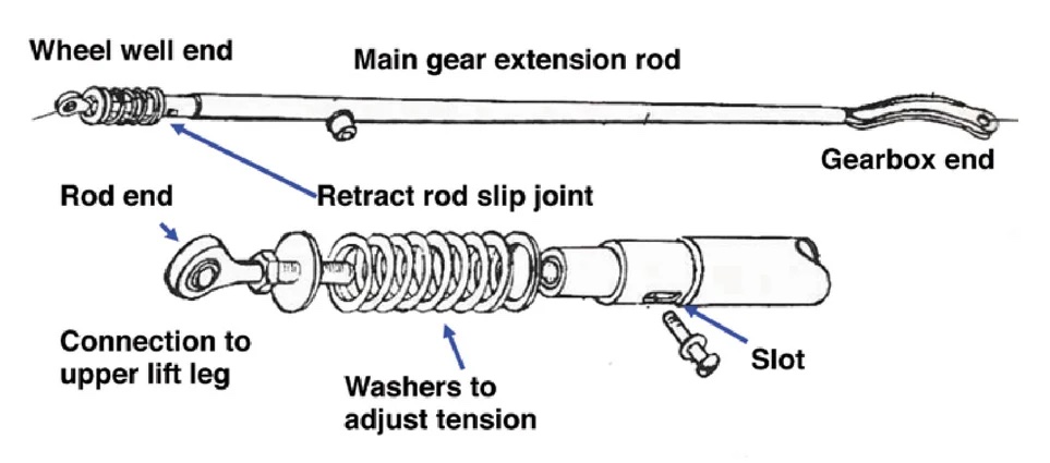
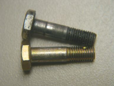
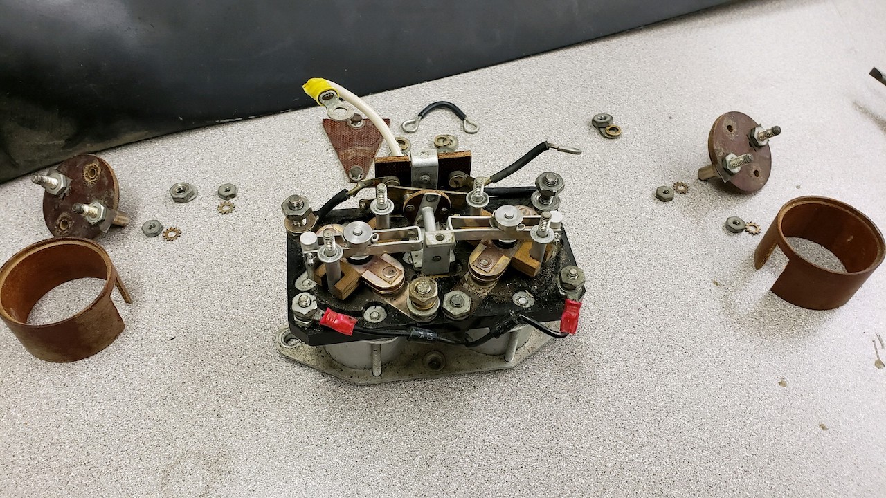
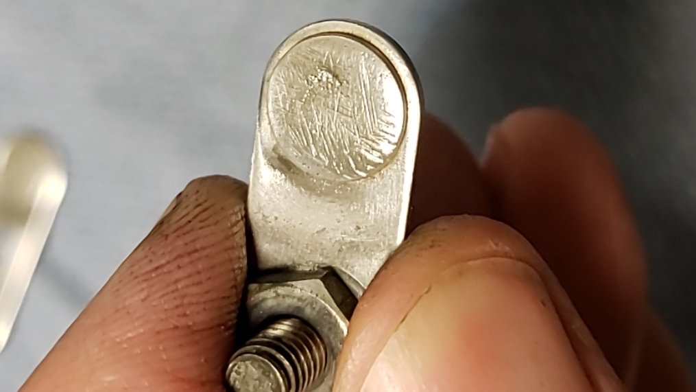
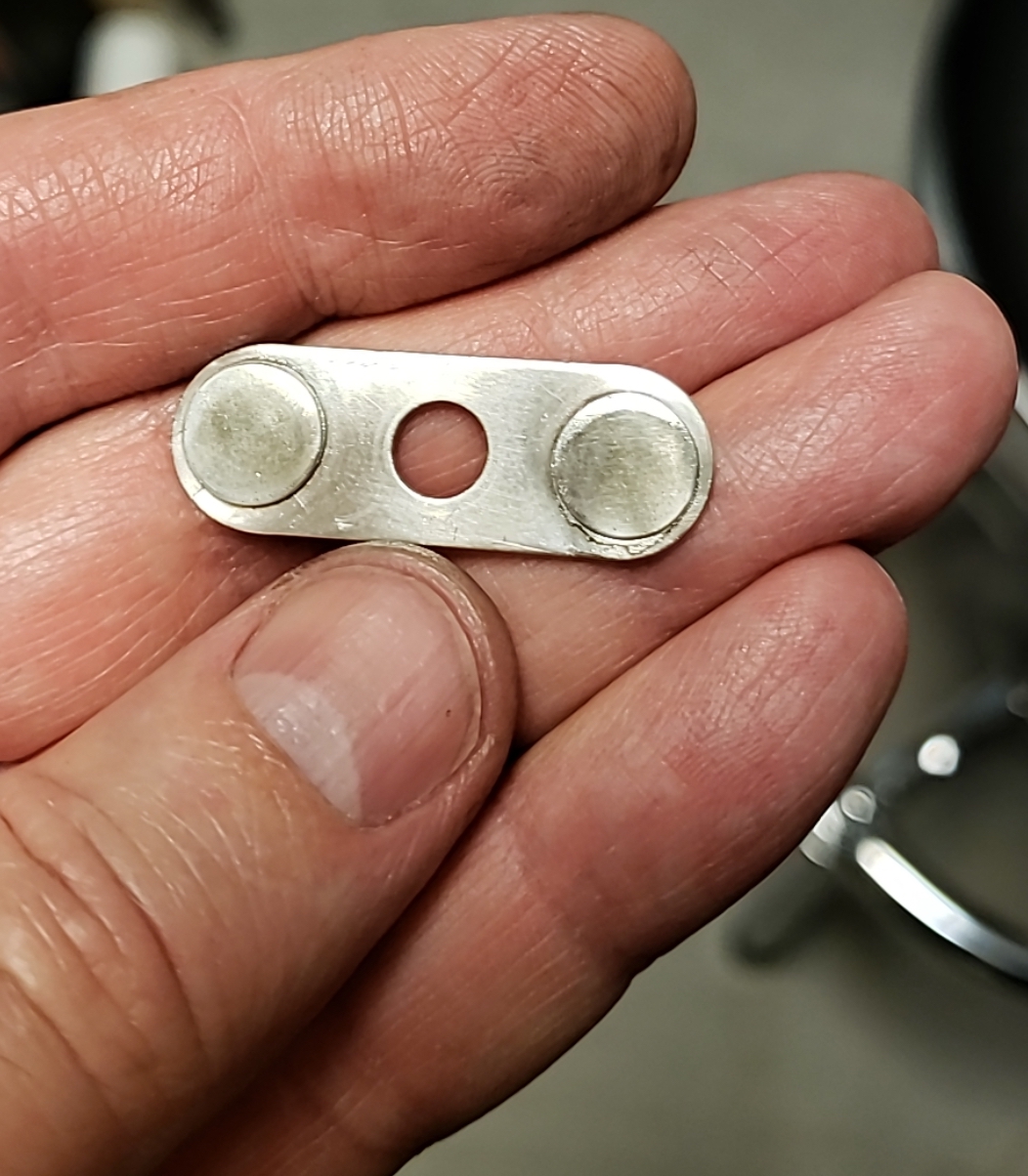
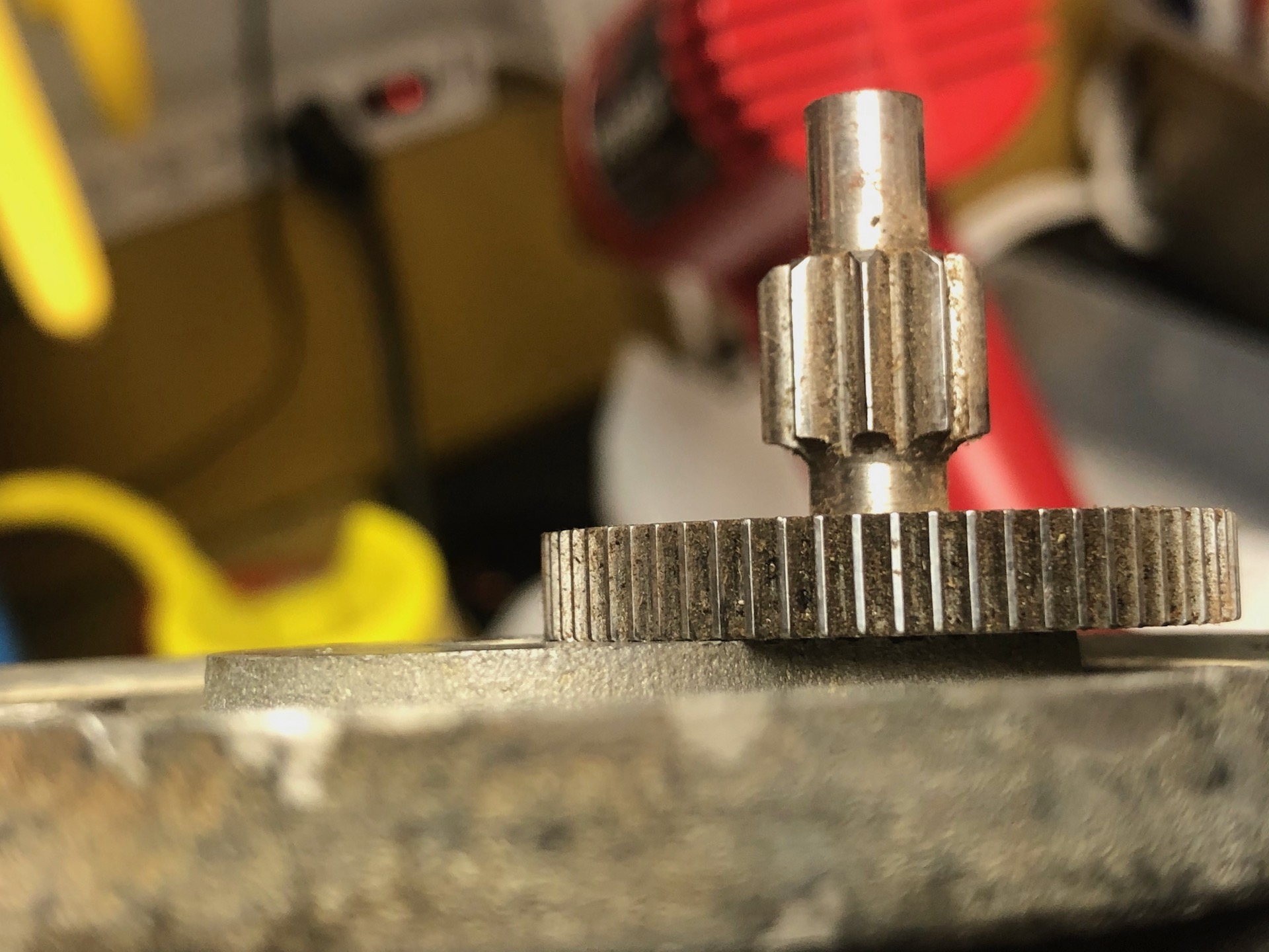
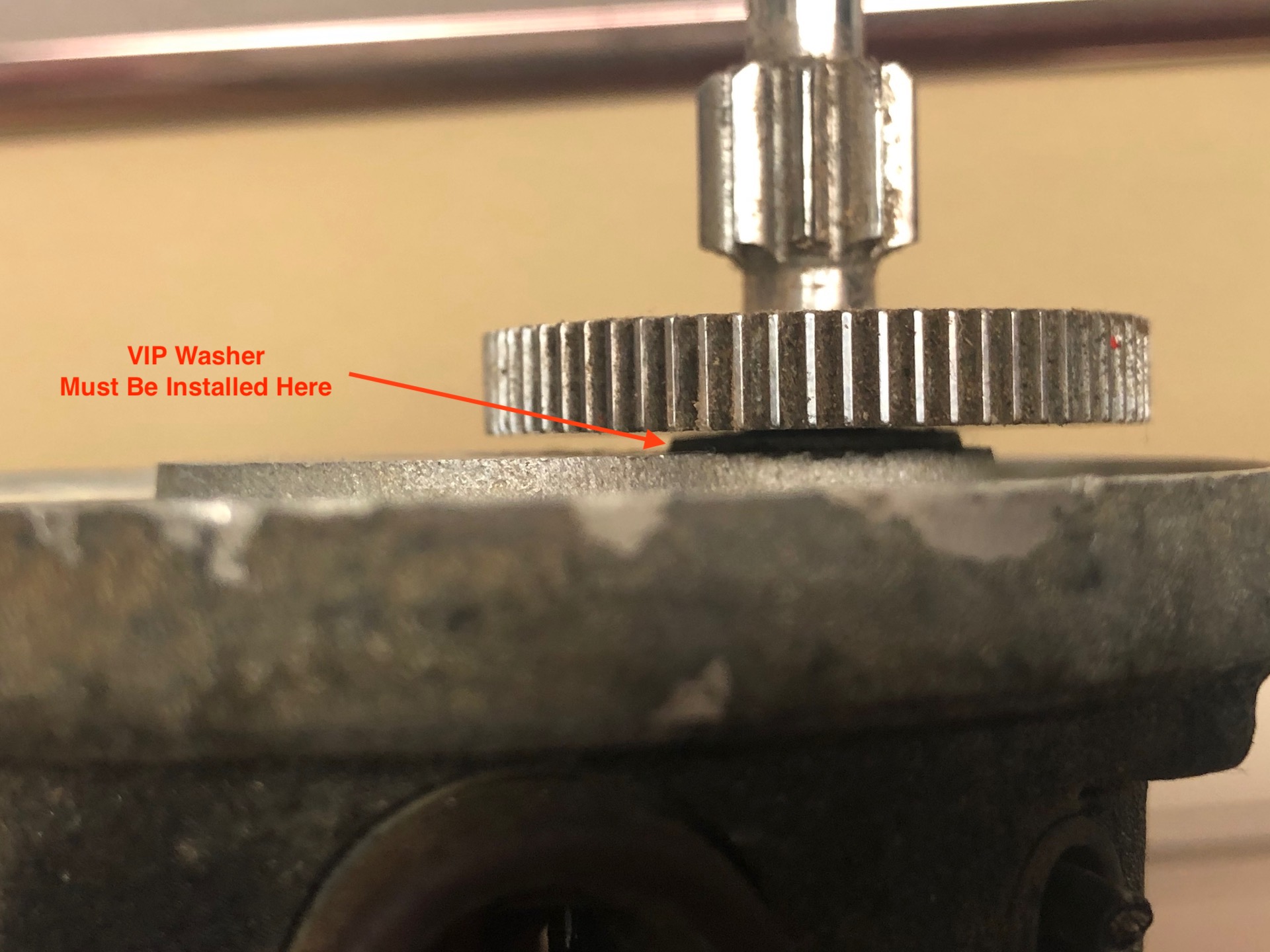
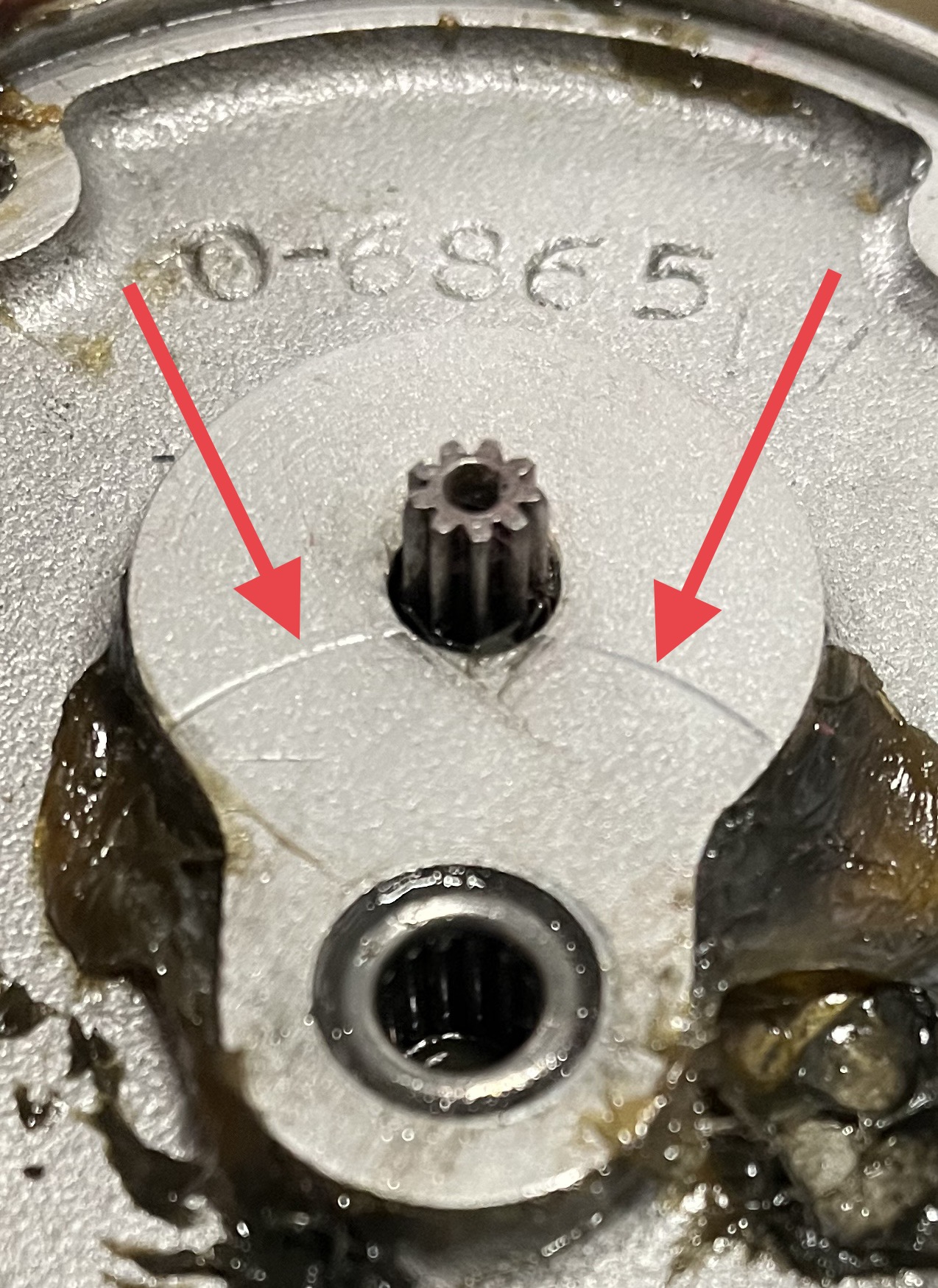
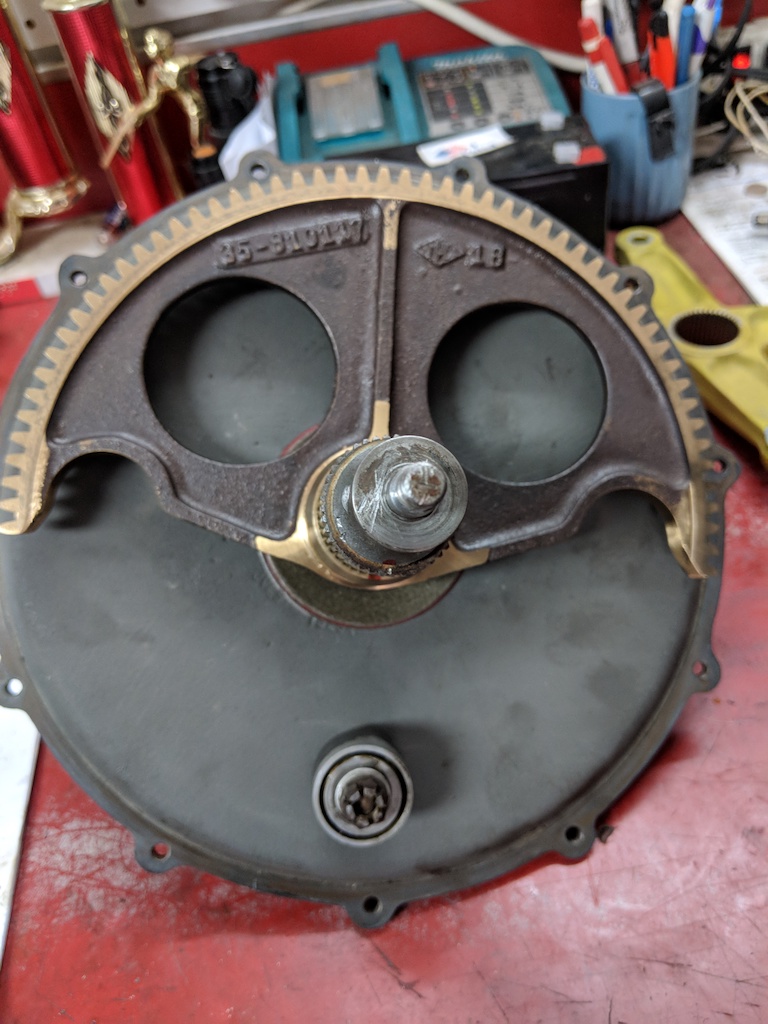
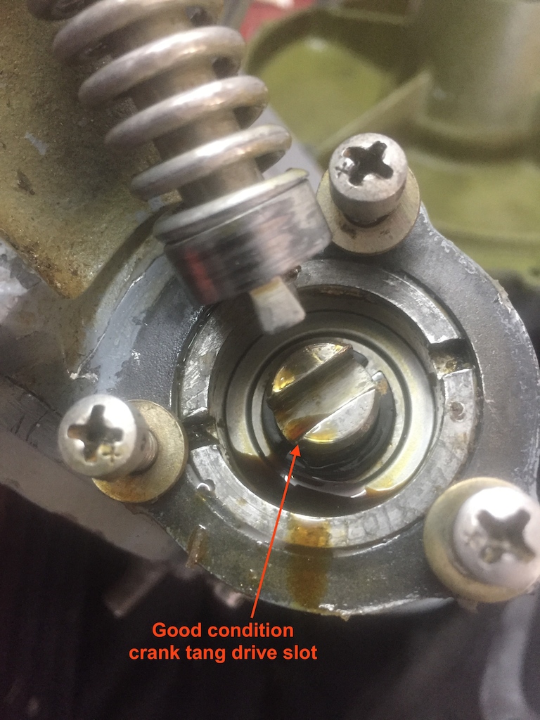
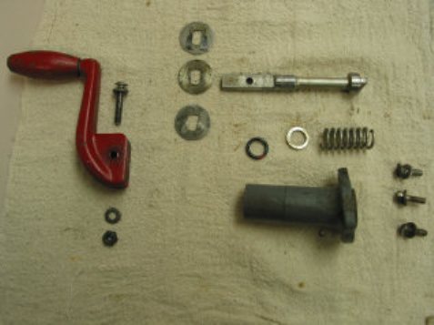
The below pictures can help readers visualize my
gear transmission extraction experience and all the gory details of my process!